
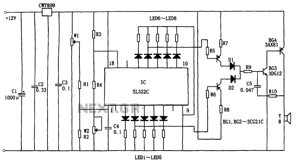
Hydraulic oil Automotive LED Alarm SL322C schematic
If the oil pressure sensor resistance W2 and resistors R3 and R4 are suitably adjusted, under normal hydraulic oil conditions, the voltage at pin 17 of the SL322C should exceed 3V, ensuring that at least four LEDs remain lit. However, if the oil pressure falls below 1.5 kg/cm², the voltage at pin 17 drops below 1V, resulting in the extinguishing of four LEDs. The alarm circuit comprises an OR gate circuit formed by components G1 and BG2, which can trigger an alarm sound from speaker Y in cases of low hydraulic oil or insufficient oil in the tank. The oscillators formed by BG3 and BG4 will only operate when BG1 and BG2 are conducting, causing BG2 to maintain a high potential at its base and thus generating audio signals. The LED display for hydraulic oil levels consists of five LEDs, which can be configured in different colors.
Typically, automotive oil level indicators may vary based on operating conditions and may not provide high accuracy, particularly in scenarios such as climbing or tilting, where the indicator's pointer may show erroneous readings. This system provides a reliable alarm to alert the driver in advance, enhancing safety and functionality. In addition to indicating the oil level, the LEDs also serve to display oil pressure status, representing a novel hydraulic oil LED alarm solution.
The schematic of this hydraulic oil alarm circuit integrates several components for effective monitoring and alerting. The SL322C serves as the primary control unit, processing inputs from the oil level sensors and driving the LEDs based on the oil level status. The CW7809 voltage regulator ensures stable operation of the circuit by providing a consistent voltage supply, essential for accurate sensor readings. The design includes resistors R1, R2, R3, and R4, which are critical for calibrating the sensor inputs to the SL322C, ensuring that the voltage thresholds are met for proper LED activation.
The alarm functionality is a crucial aspect of the design, as it uses the output from the SL322C to trigger audio signals via the speaker Y, alerting the driver to low oil levels or pressure. The circuit's use of an OR gate configuration allows for simultaneous monitoring of both oil level and pressure, enhancing the reliability of the system. The oscillators BG3 and BG4 provide the necessary audio feedback when conditions are met, ensuring that the driver is always informed of the hydraulic oil status.
This hydraulic oil alarm circuit stands out due to its dual functionality of monitoring both oil level and pressure, providing a comprehensive solution for automotive applications. The incorporation of LEDs not only serves as a visual indicator but also enhances the overall user experience by providing clear and immediate feedback regarding the hydraulic oil system's status. As shown in FIG hydraulic oil for automotive LED alarm circuit. The circuit consists of a light emitting diode driver SL322C (IC), integrated voltage regulator circuit CW7809 ( N), the hydraulic oil level sensor W (W1, W2), the alarm circuit. IC is used to display a DC signal, CW7809 the 12V battery voltage stable at 8V, in order to eliminate the influence of voltage fluctuations. If the oil level sensor W1 and resistors R1, R2 reasonably fit, the top surface of the oil tank when the voltage at the input of O feet SL322C is 3.5V, namely five light-emitting diode lighting one.
And when the oil tank minimum voltage SL322C O foot in less than 1V, then at least four LED lights, and leads to an alarm signal from the fourth light-emitting diodes, to inform the driver in advance. LED lights only the fifth time. It indicates that the oil tank has been depleted. If the oil pressure sensor resistance W2 and resistors R3, R4 reasonably fit, then under normal circumstances, hydraulic oil, the other input voltage SL322C 17 feet higher than 3V, so as to ensure that at least four LED lights, and in the oil pressure falls below l.5kg/cm2, the voltage drops below 17 feet of 1V, and there are four LED goes out, and from the fourth cormorant Farm hollow mistaken sleet lotus cow Yun Kong Mountain case Ma turnip thin Hui Qian oR gate circuit G1 and BG2 composition.
Whether it is lack of hydraulic oil, or the oil tank is too low can make the speaker Y alarm sound. When BG3 and BG4 composition oscillators, only BG1 and BG2 conduction, BG2 and the base at a high potential, the oscillator was oscillating, thereby providing audio signals Y.Hydraulic oil level display and light-emitting diode displays have five, according to the choice of a different color. In general automobile tank, oil indicating instrument vary according to operating conditions and the accuracy is not high, such as a car or climbing tilted, indicating the oil level indicating instrument pointer errors occur.
Further indicating instrument striking enough. No limit alarm to alert the driver in advance. In addition to the alarm LEDs to show the height of the oil tank and the police, it can also display oil pressure situation, it is a new type of hydraulic oil LED alarm.
Related Circuits

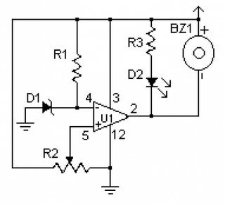
When the protective circuit is interrupted (opened), the alarm sounds. To set the circuit, adjust R2 (with the protective circuit open) for 1 V across R1. The described circuit functions as a protective alarm system that activates when the integrity...
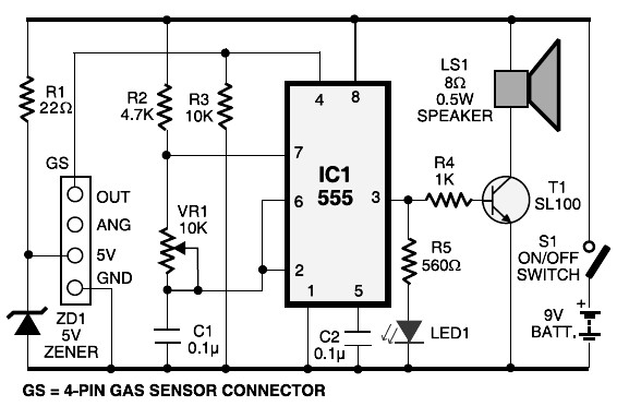
This schematic diagram represents an LPG gas leakage sensor alarm circuit powered by a 9V PP3 battery. A Zener diode (ZD1) is utilized to convert the 9V input into 5V DC, which is required to operate the gas sensor...
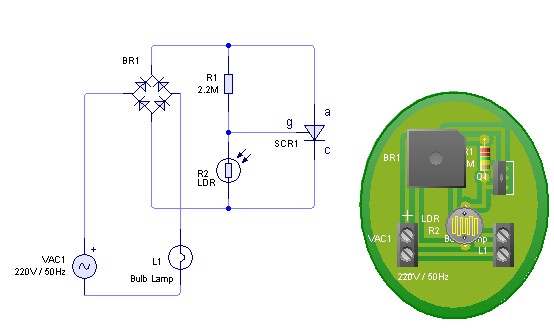
Adjust the value of R1 to achieve optimal performance of the LDR sensor. If, in practice, a resistance of 2.2 MΩ still activates the lamp, it is possible to increase the value of R1 to a larger resistance of...
A low voltage monitor circuit is essential for security and protection against potential damage to equipment, particularly for vehicles. This circuit is relatively simple to construct, utilizing the LM339 integrated circuit. The operation of this circuit involves activating a...
Power this project from sunlight with a CirKits solar power circuit board kit. Other LED lamp circuits can be seen at FC's Solar Circuits, another interesting LED project is my 13 Color LED Rainbow. This circuit makes a nice...
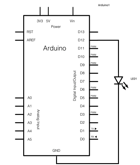
The schematic for this project consists of adding a single 5mm LED to one digital output port on the Arduino. The main components in the schematic include the Arduino Uno, a 5mm LED, and a USB cable. The left...