
LPG Gas Leakage Sensor Alarm

The LPG gas leakage sensor alarm circuit is designed to detect the presence of gas and alert users through an audible alarm. The circuit is powered by a 9V PP3 battery, ensuring portability and ease of installation in various locations. The Zener diode (ZD1) plays a critical role in regulating the voltage supplied to the gas sensor module, ensuring that it operates within its specified voltage range. The SEN-1327 gas sensor module is sensitive to LPG and provides an analog output that increases in voltage as gas concentration rises. This output can be directly interfaced with a microcontroller or used to trigger a relay.
The integration of an alarm circuit enhances the functionality of the gas leakage sensor. When the gas sensor detects an abnormal level of gas, it activates a relay that can drive a loudspeaker or alarm system to alert individuals nearby. This feature is essential for ensuring safety in environments where gas leaks can pose significant risks.
In addition to the gas leakage detection capabilities, the circuit can be combined with a fire alarm system. The fire alarm circuit utilizes an LDR, which changes resistance based on the intensity of light, particularly in the presence of smoke. This characteristic allows for the detection of smoke particles, which often accompany fire, thus providing an early warning system.
Furthermore, the NE555 timer-based fire alarm circuit employs a thermistor to monitor temperature changes. The thermistor's resistance decreases as temperature rises, allowing the NE555 timer to trigger an output when a predetermined temperature threshold is exceeded. This circuit provides an additional layer of safety by detecting fires based on temperature rather than solely on smoke presence.
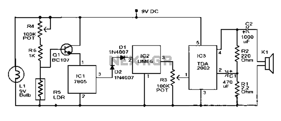
Overall, these circuits play a vital role in enhancing safety measures by providing timely alerts for gas leaks and fire incidents. The combination of gas and fire detection systems ensures comprehensive protection in residential and commercial environments.This is the schematic diagram of LPG gas leakage sensor alarm. The circuit operates off a 9V PP3 battery. Zener diode ZD1 is applied to convert 9V into 5V DC to drive the gas sensor module. The SEN-1327 gas sensor module from RhydoLABZ is applied in this circuit. Its output goes higher when the gas. Flame, gas and smoke detector for fire alarm. Y ou can combine this circuit with alarm circuit. The output will be the relay which switch on and switch off the alarm. Schematic diagram: The list of components needed: Download include the explanation of the circuit: Download link This is the fire alarm circuit which use LDR to sense the smoke from the fire, so it can be used to detect any dark smoke. With the onset of summer season, possibilities of fire accidents go up. These fire accidents could be prevented if timely alarms are available. The circuit given right here alerts. The following circuit is a simple fire alarm circuit based NE555 timer and use thermistor as a temperature detector.
This sensor will activate the transistor when the temperature is in high value. The thermistor will have a low resistance at high temperature, while at low temperature, the transistor resistance is high. This characteristic of thermitor. 🔗 External reference
Related Circuits

The LM35 temperature sensor outputs 10 mV/C for each degree Celsius above 0°C. At 20°C, the output voltage is calculated as 20 × 10 = 200 mV. The circuit consumes minimal power. Additionally, the load resistance should not be...

The primary objective is to present the circuit diagram and describe the software utilized. A UDP application is employed to transmit commands to the microcontroller, which subsequently activates or deactivates the relay. It is anticipated that TCP implementation could...
This document outlines a basic fire alarm circuit utilizing an LDR (Light Dependent Resistor) for fire detection. The circuit is designed to generate an audible alarm in response to smoke, which affects the LDR's resistance. In the absence of...

This acoustic sensor was originally developed for an industrial application (monitoring a siren), but it will also find many domestic applications. The sensor is designed with safety of operation as the top priority, meaning that in the worst-case scenario...

The circuit diagram represents an ultra-sensitive intruder alarm. A shadow from an intruder passing nearby is sufficient to trigger the alarm. The operational amplifier IC2 (uA 741) is configured as a sensitive comparator, with its set point determined by...

The circuit shown below is a basic latching circuit consisting of a quad 2-input NAND Gate IC. It is configured such that the flip flop circuit U1A and U1B has both its input held at logic "1". Pin 1...