
Arduino Blinky LED Intro Circuit
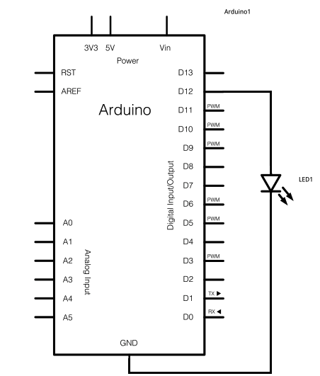
The schematic involves a straightforward connection of a 5mm LED to the Arduino Uno's digital output pin 12. The LED is a simple light-emitting diode that requires a forward voltage to operate correctly. In typical applications, a current-limiting resistor is used in series with the LED to prevent excessive current that could damage the component. However, for short-term testing purposes, the LED can be directly connected to the digital output pin, as the Arduino's output is designed to handle the current for brief periods without causing harm.
The Arduino Uno serves as the microcontroller platform, featuring an ATMega328P microcontroller, which is programmed via the Arduino IDE. The USB connector allows for easy programming and power supply, while the DC power jack enables mobile operation when an external power source is connected. The schematic illustrates the connection from the digital output pin to the anode of the LED, with the cathode connected to the ground. This configuration allows the LED to illuminate when the output pin is set to HIGH.
For testing purposes, a simple Arduino sketch can be uploaded to toggle the state of digital output pin 12. This sketch could include basic commands such as `digitalWrite(12, HIGH)` to turn on the LED and `digitalWrite(12, LOW)` to turn it off. This demonstration serves as a basic introduction to digital output control, showcasing the fundamental principles of interfacing components with the Arduino platform. The simplicity of this project makes it an excellent starting point for those new to electronics and programming with Arduino.The schematic for this project really only consists of adding a single 5mm LED to one digital output port on the Arduino. The picture below should be fairly self explanatory for how to do it. The main parts in the schematic are the Arduino Uno, 5mm LED and USB Cable. The far left side of the Arduino board (as seen above) has both the DC power j ack to supply power for mobile operation and the USB connector for supply power + programming. This USB connector actually connects to a seperate Atmel microcontroller which acts like a translator to convert USB to serial information passed on to our ATMega328 that the Arduino bootloader understands. The 5mm LED that we will add to the digital output 12 will be used to help prove that we can run both a standard example program and a modified Arduino program.
Normally a current limiting resistor should be placed before LEDs, in this case since we won`t be using the LED or Arduino in this configuration for months on end, the LED will not be damaged by connecting straight to a digital output. This is the platform that I am using, however you are free to use any of the standard Arduino platforms as they all have similar features and you can follow along with this article no matter which one you have.
🔗 External reference
Related Circuits

The high-temperature alarm will emit a beep and the LED will blink when the temperature of the device rises abnormally. This simple overheating alarm is designed to monitor heat levels. The high-temperature alarm circuit is an essential safety device used...

The circuit for the LED solar lantern lights is designed using a 6V/1W solar panel (photovoltaic panel) and a 4V/800mAh lead-acid battery. The schematic for the LED solar lantern circuit incorporates a solar panel that converts sunlight into electrical energy....

The circuit consists of two synchronized multivibrators formed by a pair of 555 timer circuits. It is capable of generating two synchronized pulse signals, with the spacing and frequency adjustable by modifying the time constant. The circuit offers flexibility...
The following circuit illustrates a Lie Detector Circuit Diagram. Features include a capacitor that eliminates the 50Hz induced mains hum present in the circuit. The Lie Detector Circuit operates on the principle of measuring physiological responses, typically galvanic skin response...

This weblog focuses on electronic circuit schematics, PCB design, DIY kits, and diagrams for electronic projects. A simple circuit utilizing the NE555 IC is presented, which can be employed to generate metronomes. This circuit is particularly beneficial for music...

This is a differentiator circuit. This circuit can be used to perform differential operations. There are two types of differentiators: the true differentiator and another type. A differentiator circuit is designed to output a voltage that is proportional to the...
Warning: include(partials/cookie-banner.php): Failed to open stream: Permission denied in /var/www/html/nextgr/view-circuit.php on line 713
Warning: include(): Failed opening 'partials/cookie-banner.php' for inclusion (include_path='.:/usr/share/php') in /var/www/html/nextgr/view-circuit.php on line 713