
Hydraulic system

The hydraulic drive system operates on the principle of Pascal's law, which states that pressure applied to a confined fluid is transmitted undiminished throughout the fluid. This principle allows for the efficient transfer of force, making hydraulic systems particularly effective in applications requiring significant mechanical advantage. The generator component, typically a hydraulic pump, is critical for creating the necessary pressure within the system. It can be driven by various power sources, including electric motors, combustion engines, or renewable sources such as windmills, allowing for versatility in design and application.
The control of the hydraulic fluid flow is managed through a series of valves and filters, which ensure that the system operates smoothly and efficiently. These components are essential for directing the flow of hydraulic fluid to the motor or hydraulic cylinder, allowing for precise control over the machinery's operation. The motor, which can be a hydraulic motor or a hydraulic cylinder, converts the hydraulic energy back into mechanical energy, enabling the machinery to perform its intended function.
Hydraulic cylinders are particularly noteworthy for their ability to generate high linear forces with relatively simple designs. They are utilized in a variety of applications, from industrial presses to construction equipment, where high force output is required. The design of hydraulic cylinders can vary significantly, with options for single-acting or double-acting configurations, depending on the specific application requirements. The ability to customize hydraulic cylinders for specific pressure ratings and stroke lengths further enhances their utility in diverse engineering applications.
In summary, hydraulic drive systems provide a robust solution for transmitting power in various mechanical applications, leveraging the principles of fluid dynamics and pressure to achieve high efficiency and force output. The continued development of hydraulic technology, alongside advancements in electric drive systems, ensures that hydraulic solutions remain relevant and competitive in modern engineering contexts.A hydraulic or hydrostatic drive system or hydraulic power transmission is a drive or transmission system that uses hydraulic fluid under pressureto drive machinery. The term hydrostatic refers to the transfer of energy from flow and pressure, not from the kinetic energy of the flow.
Such a system basically consists of three parts. The generator (e. g. a hydraulic pump, driven by an electric motor, a combustion engine or a windmill ); valves, filters, piping etc. (to guide and control the system); the motor (e. g. a hydraulic motor or hydraulic cylinder ) to drive the machinery. Pascal`s law is the basis of hydraulic drive systems. As the pressure in the system is the same, the force that the fluid gives to the surroundings is therefore equal to pressure x area.
In such a way, a small piston feels a small force and a large piston feels a large force. The same counts for a hydraulic pump with a small swept volume, that asks for a small torque, combined with a hydraulic motor with a large sweptvolume, that gives a large torque. By throttling the fluid between generator part and motor part, or by using hydraulic pumps and/or motors with adjustable swept volume, the ratio of the transmission can be changed easily.
In case throttling is used, the efficiency of the transmission is limited; in case adjustable pumps and motors are used, the efficiency however is very large. In fact, up to around 1980, a hydraulic drive system had hardly any competition from other adjustable (electric) drive systems.
Nowadays electric drive systems using electric servo-motors can be controlled in an excellent way and can easily compete with rotating hydraulic drive systems. Hydraulic cylinders are in fact without competition for linear (high) forces. For these cylinders anyway hydraulic systems will remain of interest and if such a system is available, it is easy and logical to use this system also for the rotating drives of the cooling systems.
Hydraulic cylinders (also called linear hydraulic motors) are mechanical actuators that are used to give a linear force through a linear stroke. A hydraulic cylinder is without doubt the best known hydraulic component. Hydraulic cylinders are able to give pushing and pulling forces of millions of metric tons, with only a simple hydraulic system.
Very simple hydraulic cylinders are used in presses; here the cylinder consists out of a volume in a piece of iron with a plunger pushed in it and sealed with a cover. By pumping hydraulic fluid in the volume, the plunger is pushed out with a force of plunger-area * pressure.
More sophisticated cylinders have a body with end cover, a piston-rod with piston and a cylinder-head. At one side the bottom is for instance connected to a single clevis, whereas at the other side, the piston rod also is foreseen with a single clevis.
The cylinder shell normally has hydraulic connections at both sides. A connection at bottom side and one at cylinder head side. If oil is pushed under the piston, the piston-rod is pushed out and oil that was between the piston and the cylinder head is pushed back to the oil-tank again. Simple hydraulic cylinders have a maximum working pressure of about 70 bar, the next step is 140 bar, 210 bar, 320/350 bar and further, the cylinders are in general custom build.
The stroke of a hydraulic cylinder is limited by the manufacturing process. The majority of hydraulic cylinders have a stroke between 0, 3 and 5 metres, whereas 12-15 metre stroke is also possible, but for this length only a limited number of suppliers are on the market. In case the retracted length of the cylinder is too long for the cylinder to be build in the structure.
In this case telescopic cylinders can be used. One has to r 🔗 External reference
Related Circuits
The YouTube video below demonstrates the quick and easy setup of the system at the launch site. The provided description indicates a focus on the efficiency of system installation at a launch site, as showcased in a YouTube video. In...
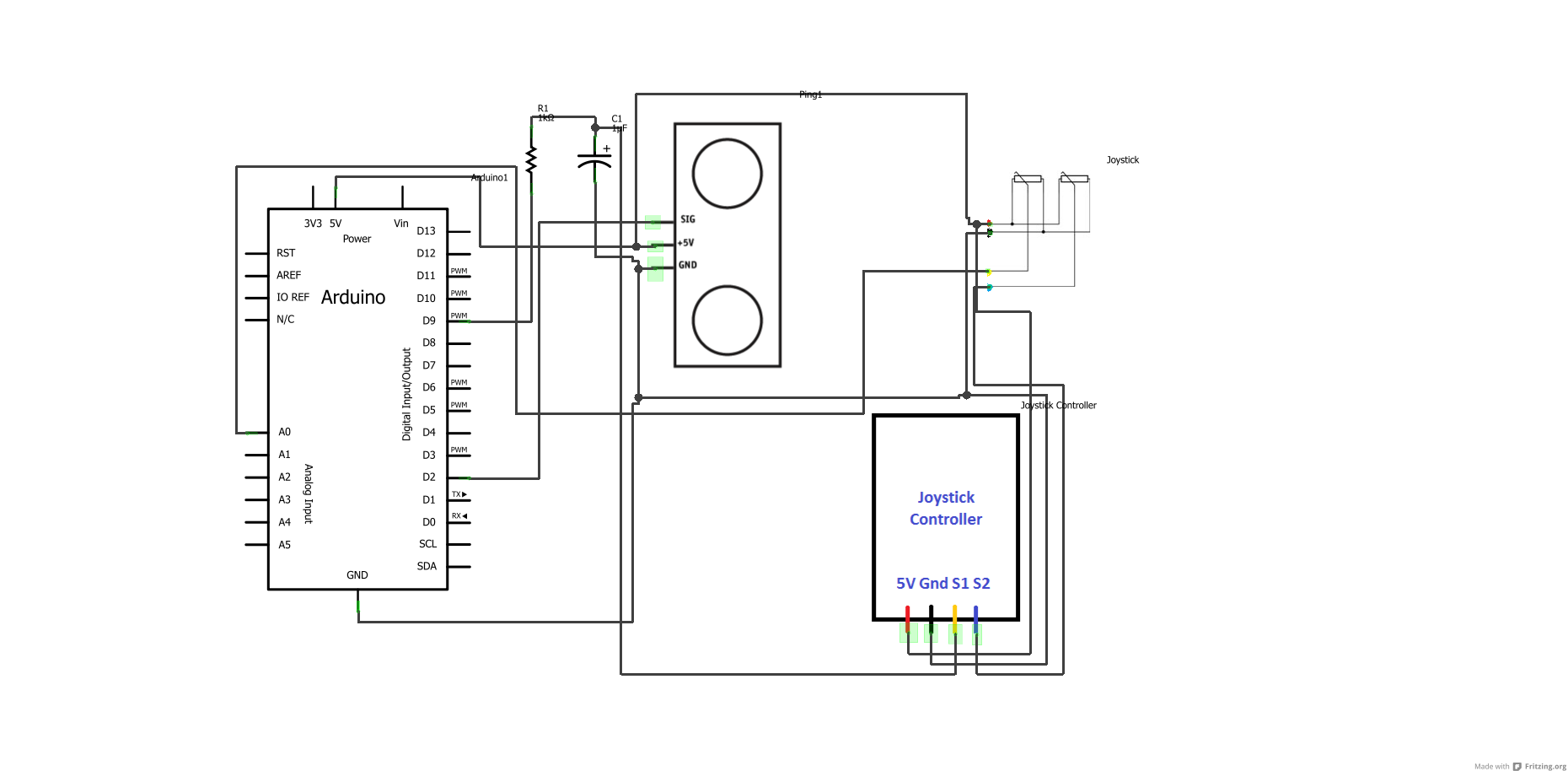
First, download any version of the Arduino software (the latest version is recommended) using the provided link, and then download the specified Arduino sketches. After the download is complete, open the sketches to view the written code. Complete the...
This document discusses a do-it-yourself alarm system utilizing the PIC18F452 microcontroller. It is a highly engaging project, although the schematic is quite complex. The project employs three main components to create the personal alarm system. The infrared (IR) proximity...
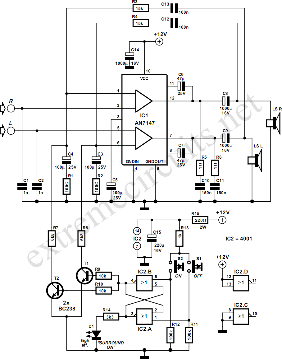
The AN7147 Dual 5.3-watt Audio Power Amplifier from Panasonic is categorized as a replacement type, indicating its anticipated availability in the market for an extended period. When combined with additional components, it can be configured to create a simple...
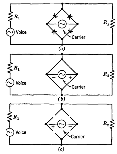
The Type C system was first installed around 1925 and has been extensively utilized since then. It incorporates the most desirable features of previously considered systems. Similar to the Type A system, the carrier signal is suppressed, minimizing the...
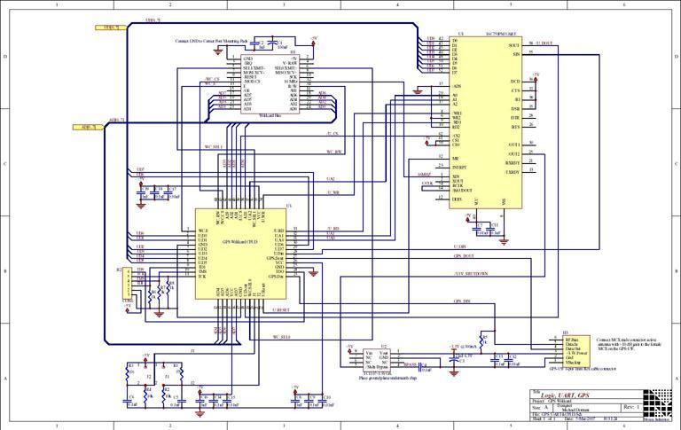
The Global Positioning System (GPS) relies on more than two dozen satellites orbiting the Earth. Each satellite transmits signals that include precise clock information and satellite position data, enabling a GPS receiver to determine its location, speed, and direction....