
Dual-Motor SIP&PUFF Controlled Kayak System
The provided description indicates a focus on the efficiency of system installation at a launch site, as showcased in a YouTube video. In an electronic schematic context, this could refer to the configuration of various components and subsystems necessary for a launch operation.
A comprehensive setup at a launch site typically involves numerous electronic systems, including telemetry, communication, power distribution, and control systems. Each subsystem must be integrated seamlessly to ensure reliable operation during critical phases of the launch.
The telemetry system is responsible for collecting data from various sensors and transmitting it to ground control. This includes parameters such as temperature, pressure, and structural integrity of the launch vehicle. Communication systems enable real-time interaction between the launch team and the vehicle, ensuring that commands can be sent and data received without delay.
Power distribution is crucial, as it involves distributing electrical power from the main source to various subsystems, ensuring that each component receives the necessary voltage and current. This often includes the use of power management ICs, voltage regulators, and backup power systems to maintain functionality in case of primary power failure.
Control systems encompass the software and hardware necessary to manage the launch sequence, including ignition, thrust vector control, and payload deployment. These systems rely on microcontrollers or FPGAs programmed to execute specific tasks based on sensor inputs and predefined algorithms.
In conclusion, the quick setup of such a comprehensive electronic system at a launch site is essential for the success of the operation, highlighting the importance of meticulous planning, robust design, and efficient integration of all electronic components.Jumping ahead just a little The YouTube video below illustrates how quickly and easily the system is set up at the launch site My to.. 🔗 External reference
Related Circuits
The RF engineer occasionally needs to find an instrument that can reliably and quickly test a low-frequency quartz crystal unit. This equipment is often challenging to locate, leading engineers to consult electronic circuits handbooks for schematics that can perform...
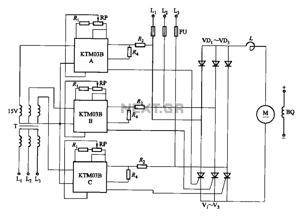
Adjusting the phase potentiometer RP can change the conduction angle of each corresponding thyristor (V1-V). This adjustment alters the voltage applied across the load. The circuit utilizes a phase control technique to manage the power delivered to a load by...
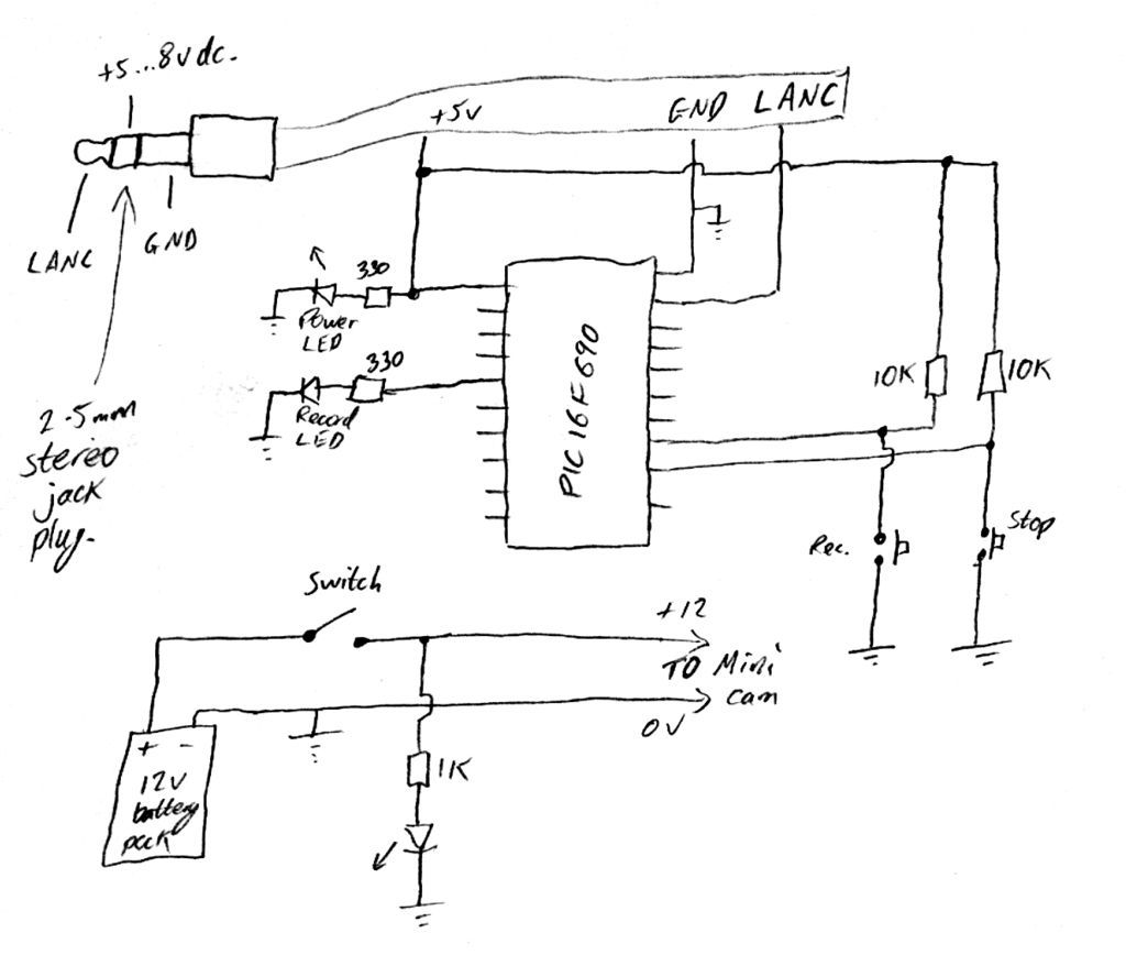
Inexpensive PIC-controlled helmet camera utilizing Sony LANC, suitable for extreme sports. This guide will demonstrate how to create an affordable helmet camera. The proposed electronic schematic involves a PIC microcontroller interfaced with a Sony LANC (Local Application Control Bus) to...
This is a schematic diagram of a micropower voltage-controlled oscillator circuit. This circuit can generate square and triangle wave outputs and only requires minimal power. The micropower voltage-controlled oscillator (VCO) circuit is designed to produce both square and triangle waveforms,...
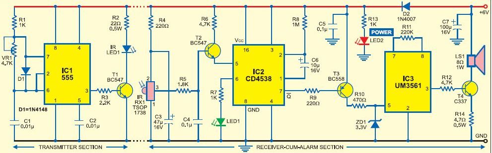
This burglar alarm system circuit utilizes an infrared proximity detector that triggers an alarm when the rays falling on its sensor are interrupted. It stands out from other burglar alarm systems due to its simplicity as a DIY project,...
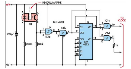
Here is how to build a pendulum-controlled clock that can be made very accurate. Retro? Yes, but it is an interesting project nonetheless. You will need a specific set of components. A pendulum-controlled clock is a mechanical timekeeping device that...
Warning: include(partials/cookie-banner.php): Failed to open stream: Permission denied in /var/www/html/nextgr/view-circuit.php on line 713
Warning: include(): Failed opening 'partials/cookie-banner.php' for inclusion (include_path='.:/usr/share/php') in /var/www/html/nextgr/view-circuit.php on line 713