
Hydrogen Generator 555 Timer Pulse Width Modulation Circuit
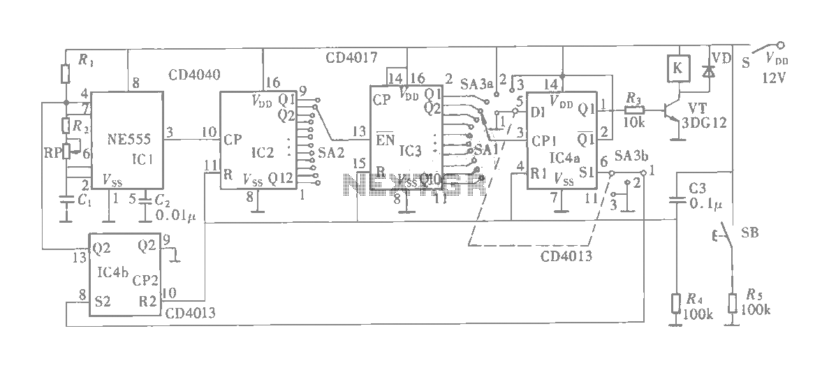
The hydrogen generator circuit utilizing a 555 timer operates by controlling the duty cycle of the PWM signal to regulate the electrolysis process. The 555 timer is configured in astable mode, producing a continuous square wave output. This output is fed to an electrolytic cell, where water (H2O) is split into hydrogen (H2) and oxygen (O2) gases through the application of an electric current.
The circuit design includes the following components: a 555 timer IC, resistors, capacitors, and an electrolytic cell consisting of two electrodes submerged in water. The resistors determine the frequency and duty cycle of the PWM signal, while the capacitor helps in stabilizing the output waveform. The duty cycle can be adjusted by varying the values of the resistors, enabling the user to control the amount of hydrogen produced.
Power supply requirements for the circuit typically range from 5V to 15V, depending on the specific design and components used. The electrolytic cell must be constructed from materials that are resistant to corrosion, such as stainless steel or graphite, to ensure longevity and efficiency.
Safety precautions should be taken when working with hydrogen, as it is highly flammable. Adequate ventilation is necessary, and the circuit should be housed in a non-combustible enclosure to prevent any fire hazards. The generated hydrogen can be collected and utilized for various applications, including fuel cells or combustion engines, demonstrating the practical utility of this PWM-controlled hydrogen generator circuit.How to Make a Hydrogen Generator 555 Timer Circuit PWM. This Pulse Width Modulation (PWM) Circuit could Produce Hydrogen on Demand.. 🔗 External reference
Related Circuits
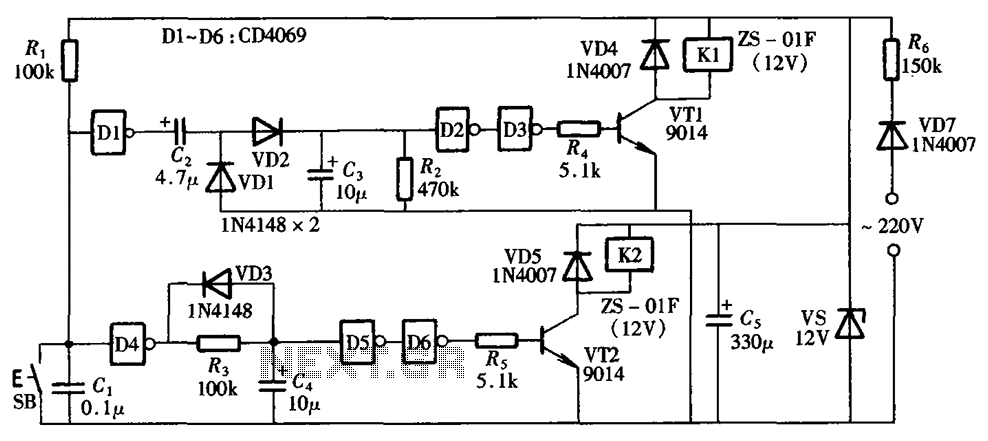
A one-button control switch is designed to control two relays, each of which can switch the load power on and off as needed. The circuit primarily consists of a hex inverter CD4049 and two self-locking DC relays. The circuit utilizes...
Although it may lack the aesthetic appeal of traditional mercury barometers, which feature long glass tubes mounted on intricately carved and polished wood, the Torricelli barometer being discussed serves as a functional equivalent and electronic replica of the classic...
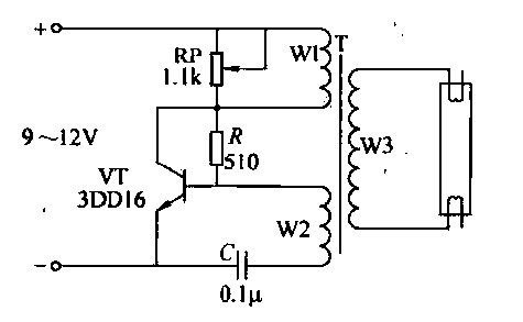
This circuit is designed for the ignition of a direct current (DC) fluorescent lamp rated between 6 to 8 watts. It utilizes a common pole-blocking oscillator that consists of a transistor (VT) and is induced by the secondary side...
This schematic represents an FM transmitter capable of delivering an output power between 3 to 3.5 W, operating within the frequency range of 90 to 110 MHz. While the stability of the circuit is acceptable, the integration of a...
The multifunction circuit primarily refers to its capability to operate in three modes: "delayed pull," "time release," and "delayed cycle." The term "delay" indicates that the relay is energized after a predetermined time; however, the relay does not activate...
This circuit measures the distance covered during a walk. The hardware is housed in a compact box that can be conveniently placed in a pants pocket. The display is designed as follows: the leftmost display, D2 (the most significant...
Warning: include(partials/cookie-banner.php): Failed to open stream: Permission denied in /var/www/html/nextgr/view-circuit.php on line 713
Warning: include(): Failed opening 'partials/cookie-banner.php' for inclusion (include_path='.:/usr/share/php') in /var/www/html/nextgr/view-circuit.php on line 713