
Multifunction adjustable universal time relay (NE555, CD4013) circuit
The multifunction circuit is designed to provide flexibility in control applications, utilizing a relay as the primary switching mechanism. In the delayed pull mode, the circuit incorporates a timer that begins counting once power is applied. The relay remains in an unenergized state until the timer reaches the predetermined alarm time, at which point the relay is activated, allowing current to flow through the connected load. This mode is particularly useful in applications where a delay is required before activating a device, such as in safety systems or time-sensitive operations.
Conversely, the delayed release mode operates by energizing the relay immediately upon power application. The relay remains engaged until the timer counts down to zero, at which point it deactivates, cutting off power to the load. This mode is beneficial for applications requiring an immediate activation followed by a controlled shutdown after a specific duration.
The delay cycle mode introduces a more dynamic operation, where the circuit alternates between on and off states based on user-defined intervals. Once powered, the relay will engage, and the timer will initiate a countdown. Upon reaching the preset stop time, the relay will disengage, and the cycle will repeat. This mode is advantageous for applications such as automated lighting systems, irrigation controls, or any system requiring periodic activation and deactivation.
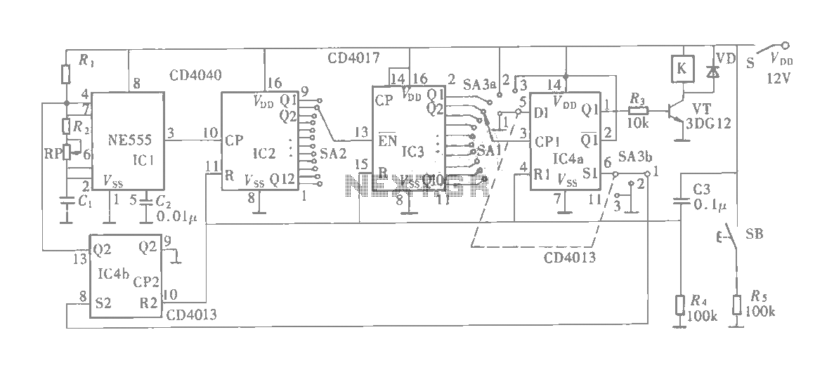
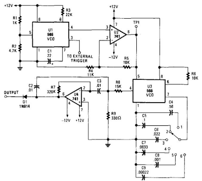
The circuit design typically includes a microcontroller or timer IC to manage the timing functions accurately. Additional components may include resistors, capacitors, and diodes to ensure stable operation and protect against voltage spikes. A visual representation of the circuit can provide insight into the interconnections and component values necessary for achieving the desired operational modes.The multifunction circuit mainly refers to it can be "delayed pull", "time release", "delayed cycle" conversion three operating modes. The so-called delay means that the relay is energized after a preset power, the relay does not pull. Only when the preset alarm time, the relay was energized. Delay and delay the release pull the contrary, after turning on the preset relay when the timer reaches the preset time, the relay releases.
Delay the closing and delayed release of the two states operate as a one-time, when the relay to complete a work process, the control portion of the circuit into a stable state. Delay cycle work as long as the state is turned on, the circuit will be a good start and the preset stop time interval automatic cycle, never stop until the power switch off or switch the operating state.
Its circuit as shown in FIG.
Related Circuits

The sound mixer circuit is designed for service applications. This mixer is straightforward to implement and cost-effective, as it consists of two transistors along with a few simple resistors and capacitors. The sound mixer circuit typically utilizes two transistors configured...
This intelligent electronic lock circuit is constructed using only transistors. To unlock this electronic lock, the user must press tactile switches S1 through S4 in sequence. For added security, these switches can be labeled with different numbers on the...
A transistor optocoupler interface circuit, as described in section 15.1.6, has been implemented. This circuit serves as a transistor interface with other circuits. The transistor optocoupler interface circuit utilizes a light-emitting diode (LED) and a phototransistor to achieve electrical isolation...
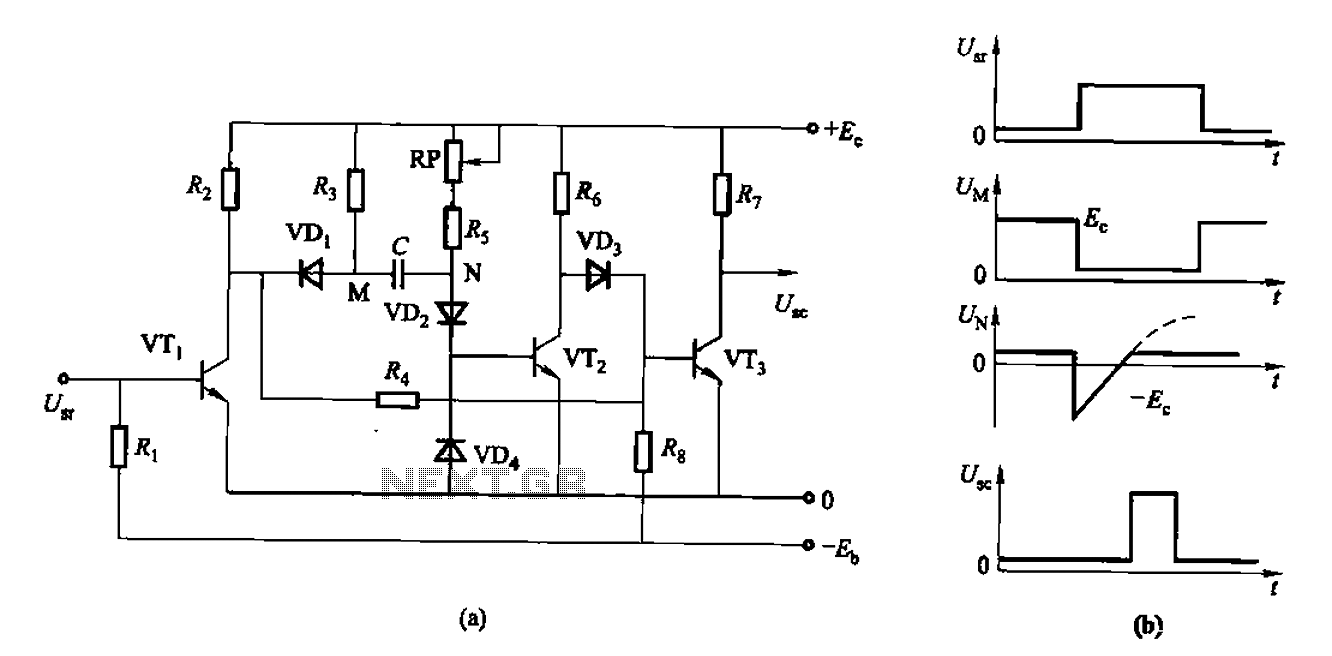
The circuit described is a discharge delay circuit that offers a longer delay compared to a standard rechargeable delay circuit, while also maintaining relatively high accuracy. The schematic diagram illustrates the input and output waveforms. Typically, when there is...
When this circuit is connected to a filter and an oscilloscope, the oscilloscope displays the filter's frequency response. A frequency that sweeps from low to high is applied to a filter. The oscilloscope is triggered by the start of...
There are two types of solar automatic tracking controllers. One type utilizes a Schmitt trigger light control, which consists of a light sensor and a Schmitt trigger or monostable trigger. The second type employs two light sensors and two...