
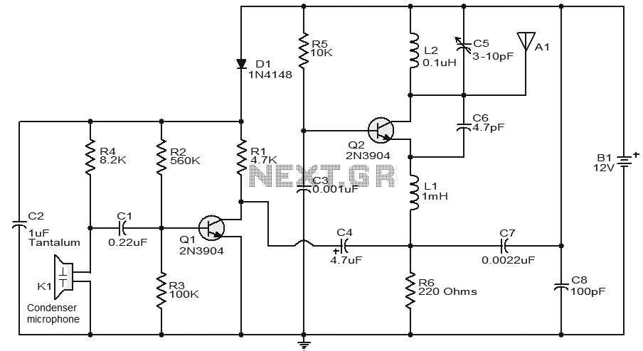
IC BA1404 For Stereo FM Transmitter
The BA1404 is a versatile integrated circuit designed specifically for FM transmission applications. It operates within a frequency range suitable for stereo audio signals and can be utilized in various projects requiring wireless audio transmission. The circuit typically includes essential components such as resistors, capacitors, and an antenna, which work together with the BA1404 to modulate audio signals onto a carrier frequency.
Key features of the BA1404 include low power consumption, which is advantageous for battery-operated devices, and built-in pre-emphasis circuitry that enhances audio quality by boosting high frequencies. The circuit can be easily assembled on a breadboard or a printed circuit board (PCB), allowing for flexibility in design and testing.
In a typical configuration, the audio input is fed into the BA1404 through a coupling capacitor, which blocks any DC components while allowing the audio signal to pass. The modulation process occurs internally, where the audio signal is superimposed onto the carrier frequency generated by the IC. The output stage of the circuit usually connects to an external antenna, which radiates the modulated signal over the airwaves.
Careful attention should be paid to the layout of the circuit to minimize interference and ensure optimal performance. Proper grounding techniques and shielding may be employed to enhance the circuit's stability and reduce noise. Additionally, selecting the appropriate values for resistors and capacitors can fine-tune the transmitter's frequency response and output power.
Overall, the BA1404 FM transmitter circuit represents an excellent project for electronics enthusiasts, providing a practical application of analog signal processing and wireless communication principles.The following circuit shows about IC BA1404 For Stereo FM Transmitter Circuit Diagram. Features: easy enough for everyone to build, has a .. 🔗 External reference
Related Circuits
This transmitter utilizes a 5089 DTMF generator chip along with a keypad to produce DTMF signals, which are then modulated onto an infrared (IR) light beam emitted from an IR LED. The circuit employs a 3.579-MHz TV burst crystal...
This circuit features a very stable and simple FM transmitter design. This transmitter can achieve a range of approximately 200 meters when properly matched. The FM transmitter circuit typically consists of several key components: an oscillator, modulator, amplifier, and antenna....
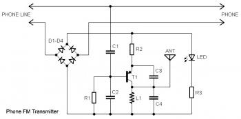
This circuit connects in series with a home phone line and transmits phone conversations through the FM band whenever the telephone handset is picked up. The transmitted signal can be tuned by any FM receiver. The circuit includes an...
A current loop transmitter refers to a sensor system utilized in industrial 4-20mA current loop technology. This transmitter contains the... A current loop transmitter is a critical component in industrial automation and control systems, particularly in applications where analog signal...
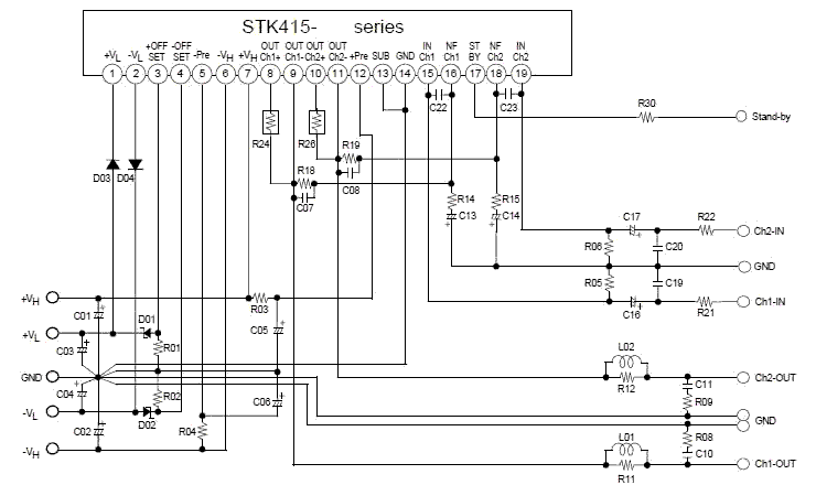
This electronic project stereo amp is based on the STK415-090-E class H audio power amplifier hybrid IC that features a built-in power supply switching circuit. This STK415-090-E class H audio power amplifier provides high efficiency audio power amplification by...
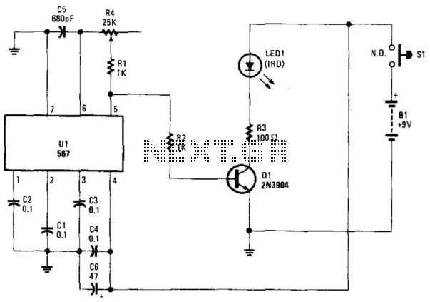
Using an NE567 as a tone oscillator, this circuit produces an infrared (IR) signal from the LED, which is modulated with a square wave. LED1 is an IR-emitting LED. The modulation enhances performance under high ambient light conditions. The circuit...
Warning: include(partials/cookie-banner.php): Failed to open stream: Permission denied in /var/www/html/nextgr/view-circuit.php on line 713
Warning: include(): Failed opening 'partials/cookie-banner.php' for inclusion (include_path='.:/usr/share/php') in /var/www/html/nextgr/view-circuit.php on line 713