
home telephone fm transmitter circuit
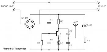
This circuit operates by integrating with the existing telephone line infrastructure, allowing for real-time audio transmission over the FM band. The series connection ensures that the circuit does not interfere with the normal operation of the phone line. When the handset is lifted, the circuit activates, and the audio signal is modulated onto an FM carrier wave. The tuning capability of any standard FM receiver allows users to select the appropriate frequency to listen to the transmitted conversation.
The "On Air" LED indicator serves as a visual cue, informing the user when the transmitter is active. This feature is particularly important for ensuring that conversations are not inadvertently broadcasted to unintended receivers. The inclusion of a switch to deactivate the transmitter allows for user control, enhancing privacy and preventing unauthorized transmission.
Powering the circuit directly from the phone line eliminates the need for an external power source, making the design more convenient and compact. The short wire aerial is designed to be efficient in transmitting the modulated signal over a limited range, suitable for local reception. Additionally, the ability of the phone line to radiate a portion of the RF signal expands the effective transmission range without compromising the integrity of the phone line itself.
While this circuit can facilitate the sharing or recording of conversations, it is imperative to note that it must be used in compliance with legal regulations governing privacy and telecommunications. The design emphasizes ethical use, ensuring that users are aware of the implications of broadcasting private conversations.This circuit connects in series with your home phone line and delivers the phone conversation through the FM band any time you pick up the telephone handset. Transmitted signal could be tuned by any FM receiver. The circuit features an "On Air" LED indicator and also gives you a switch t hat can be utilized to turn off the transmitter. A special characteristic of the circuit is the fact that no battery is required to operate the circuit because electrical power is taken from your phone line. The transmitter circuit works by using only a short piece of wire aerial about 4" / 10 cm long to transmit the signal and a portion of the RF signal can also be radiated via the phone line itself.
The circuit may possibly be implemented to share or record conversations, but will not be meant for illegal use. 🔗 External reference
Related Circuits
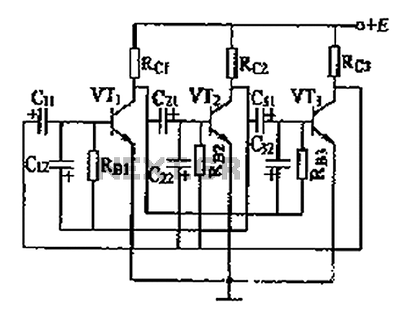
The three astable circuit is illustrated, demonstrating that each level of the transistor's base is connected by a capacitor between the two levels, ensuring tight coupling. Additionally, each base electrode is biased through a resistor (Rb) connected to the...
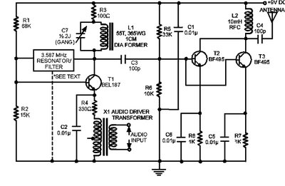
The circuit presented here is a powerful AM transmitter utilizing a ceramic resonator/filter operating at 3.587 MHz. This circuit primarily relies on a transistor for its core functionality. It is possible to use resonators/filters of other frequencies, such as...
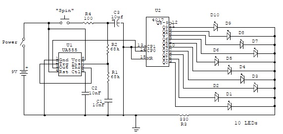
This electronic circuit is a simplified version of an electronic roulette game, utilizing the 4017 integrated circuit (IC), which functions as a 10-stage decade counter/divider. It is driven by a versatile 555 IC configured as a voltage-controlled oscillator (VCO)....
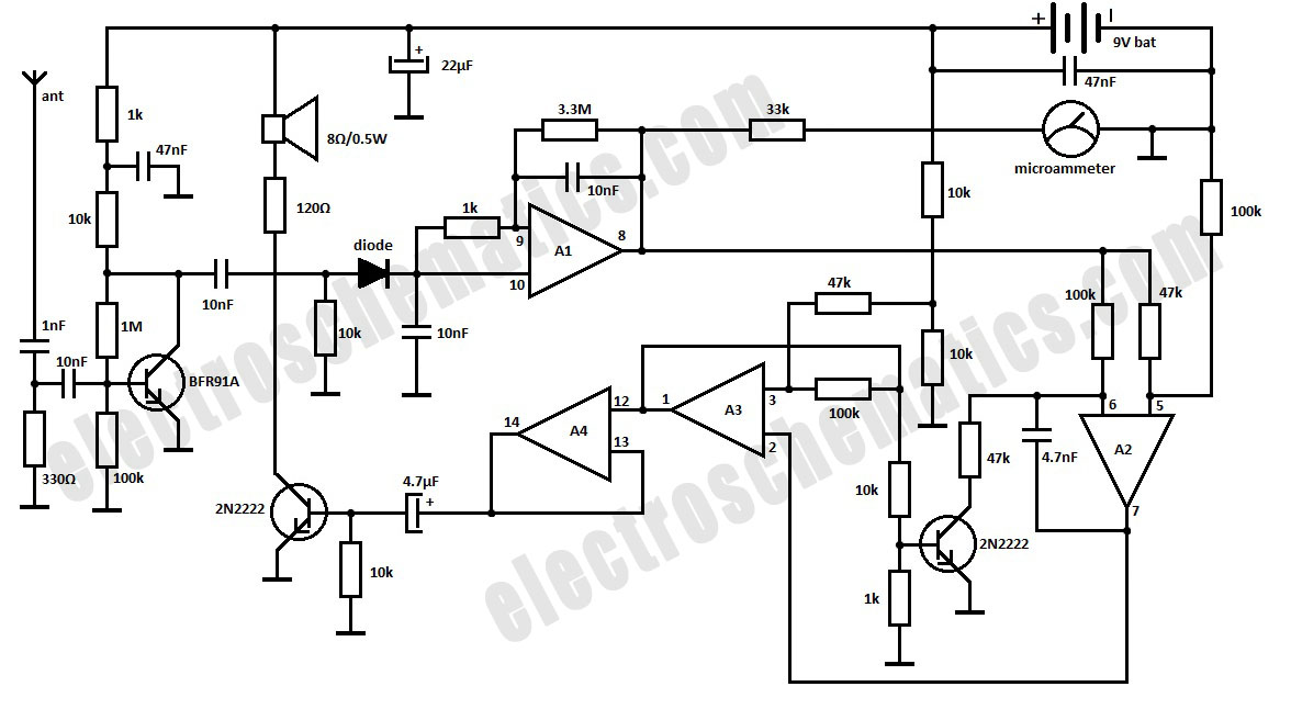
This is a simple RF bug detector designed to identify spy bugs, capable of operating up to 2 GHz. Below are some essential components required for this circuit. The RF bug detector circuit functions by utilizing radio frequency signals...
This is an upgraded circuit based on the Simple Volume Unit Display Circuit Diagram 1, featuring enhanced power for the audio input. Components include resistors. The upgraded circuit enhances the functionality of the original Simple Volume Unit Display by incorporating...
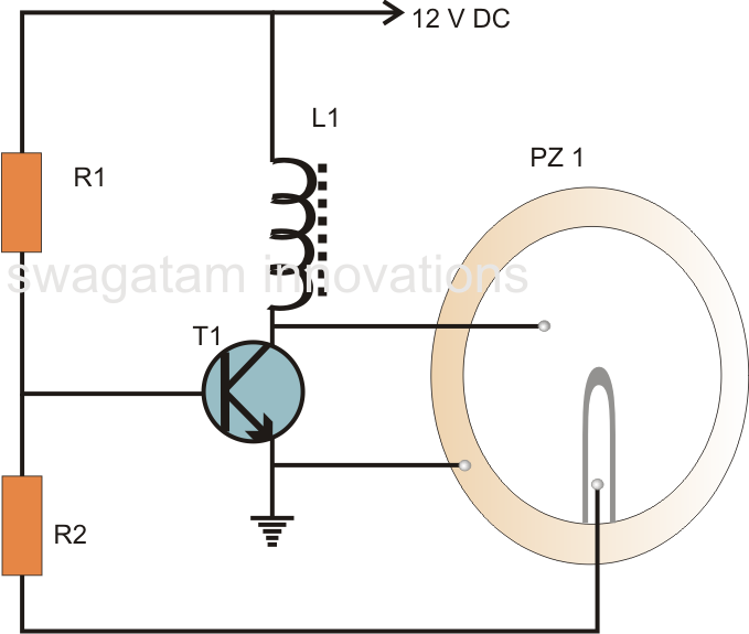
A very simple piezoelectric buzzer can be constructed with minimal electronic components, requiring just a single transistor, a coil, and a piezo buzzer to produce a sound that may be quite piercing. This buzzer circuit operates in a unique...
Warning: include(partials/cookie-banner.php): Failed to open stream: Permission denied in /var/www/html/nextgr/view-circuit.php on line 713
Warning: include(): Failed opening 'partials/cookie-banner.php' for inclusion (include_path='.:/usr/share/php') in /var/www/html/nextgr/view-circuit.php on line 713