
IC Controlled Emergency Light With Charger Circuit

The IC-controlled emergency light circuit operates by utilizing a relay, an inverter, and a battery management system. The core of the circuit is an integrated circuit (IC) that monitors the mains voltage. When the mains supply is interrupted, the IC triggers relay RL2, which then connects the battery to the inverter circuit. The inverter converts the 12V DC from the battery into 220V AC, which is suitable for powering standard household appliances.
The circuit includes a battery charger that maintains the battery's charge when mains power is available. This charger is designed with over-charge protection to prevent damage to the battery. It typically incorporates a voltage regulator and a current limiting circuit to ensure the battery is charged safely and efficiently.
The switch S1 is used to manually control the operation of the inverter, allowing for user intervention if necessary. The normally closed contacts of relay RL2 ensure that, in the event of a power failure, the battery is automatically connected to the inverter without requiring manual operation.
In summary, this circuit diagram illustrates a reliable emergency lighting solution that autonomously activates during power outages while simultaneously ensuring the battery is kept charged and protected from overcharging. This design is suitable for various applications, including residential, commercial, and industrial environments, where uninterrupted power supply is critical.Here is the circuit diagram of IC Controlled Emergancy Light With Charger or simply 12V to 220V AC inverter circuit. The circuit shown here is that of the IC controlled emergency light. Its main features are: automatic switching-on of the light on mains failure and battery charger with over-charge protection.
When mains is absent, relay RL2 is in de-energized state, feeding battery supply to inverter section via its N/C contacts and switch S1.. 🔗 External reference
Related Circuits
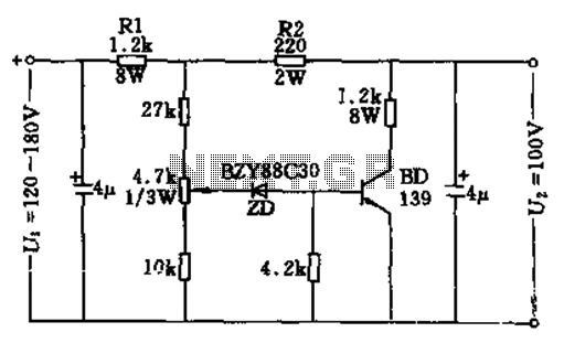
The circuit features no-load and short circuit protection mechanisms. To accommodate short circuit conditions, it is necessary to increase resistors R1 and R2 to allow for power dissipation; for example, R1 can be set to 1.2kΩ with a power...

This article discusses a simple 5-channel radio remote control circuit utilizing the TX-2B and RX-2B integrated circuits from Silan Semiconductors. The TX-2B/RX-2B is a remote encoder-decoder pair suitable for remote control applications. It features five channels, a wide operating...
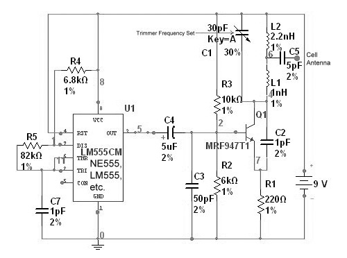
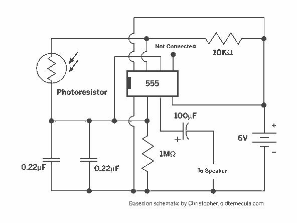
The circuit is based on the NE555 timer, functioning as a simple noise maker, with its output connected to a single transistor oscillator. This oscillator is designed to operate within a frequency range of 800 MHz to 2 GHz,...

This circuit utilizes a 4049 integrated circuit (IC) to control a 2N2222 switching transistor. The transistor, in turn, drives a piezo transducer known as crystal 1. The circuit design begins with the 4049 IC, which is a hex inverter capable...
A light Theremin constructed using an oscilloscope panel, enhanced with a Joule Thief circuit. The design incorporates a 10 K variable resistor for pitch control and a 20 K variable resistor for volume control. The circuit is powered by...
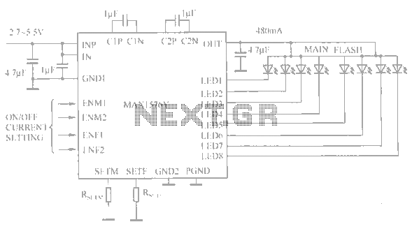
The circuit utilizes the MAX1576Y charge pump white LED driver, capable of supplying a total current of up to 480mA across two groups (n = 4 white LEDs). Each white LED in the flashing group can draw a maximum...