
Oscilliscope Theremin with Joule Thief circuit
The light Theremin is an innovative electronic musical instrument that utilizes a light sensor to detect changes in light intensity, which in turn alters the pitch of the sound produced. The core of the circuit is built around an oscilloscope panel, which visually represents the waveform generated by the Theremin. The Joule Thief circuit serves to boost the voltage from the 9 V battery, allowing for effective operation even when the battery voltage drops.
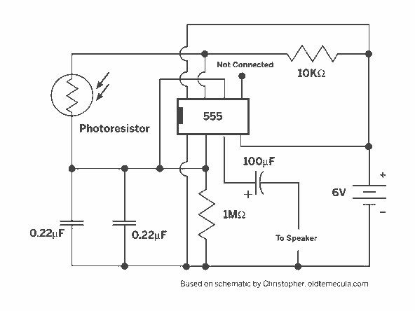
In this design, the 10 K variable resistor functions as a pitch control, allowing the user to modify the frequency of the audio output. Adjusting this resistor changes the resistance in the oscillator circuit, thereby altering the oscillation frequency and producing different pitches. The 20 K variable resistor is used for volume control, enabling the user to adjust the amplitude of the sound output. This is typically achieved by varying the feedback in the amplifier stage of the circuit.
To ensure optimal performance, it is essential to carefully select the components used in the circuit. The light sensor can be a phototransistor or a photodiode, which reacts to changes in ambient light conditions. The oscillator circuit may utilize a simple RC (resistor-capacitor) network or a more complex configuration, depending on the desired sound characteristics.
The integration of the Joule Thief circuit not only enhances the efficiency of the power supply but also allows for extended operation time from the 9 V battery. This is particularly beneficial for portable applications where battery life is a critical consideration.
Overall, the light Theremin represents a fascinating intersection of art and technology, providing users with a unique way to explore sound through light interaction. The combination of variable resistors for pitch and volume control, alongside the innovative Joule Thief circuit, creates a versatile instrument suitable for both experimental and musical applications.A light Theremin built with a oscilliscope panel with added Joule Thief. I used a 10 K variable resistor for pitch control and a 20 K variable resistor for volume control.The circuit is powered by a 9 V battery. 🔗 External reference
Related Circuits
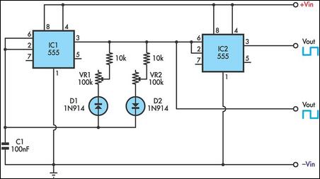
This timer utilizes two 555 integrated circuits (ICs) to adjust the desired output. The variable resistors VR1 and VR2 serve as potentiometers to modify the cycle speed. The circuit can be powered with a 9 to 12-volt power supply,...
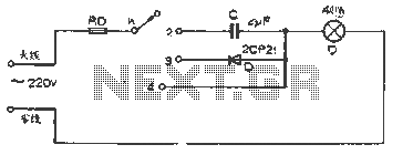
The figure illustrates a basic dimming lights circuit. The light intensity is controlled by a multi-speed control switch, designated as K. When switch K is set to position "1," the lights are turned off. In position "2," the light...

The PM4040F is utilized in switching power supply applications for medium power ranges. It is designed to drive power supplies between 200W and 800W, as illustrated in the accompanying bridge circuit. For power applications below 1000W, an alternative circuit...
The circuit presented is an integrated circuit (IC) controlled emergency light. Its key features include automatic activation of the light during mains failure and a battery charger equipped with overcharge protection. In the absence of mains power, relay RL2...
The circuit diagram illustrates a voltage regulator designed from discrete components to meet specific voltage requirements. It provides two sets of component values for output voltages of 6.3 V (upper) and 12.6 V (lower). The components used include BC547...
This digital thermometer circuit diagram utilizes a standard 1N4148 diode as the temperature sensor. The temperature coefficient of the diode is -2 mV/°C. The digital thermometer circuit leverages the characteristics of the 1N4148 diode, which exhibits a predictable voltage drop...