
5 channel radio remote control circuit based of TX-2B / RX- 2B pair

The 5-channel radio remote control circuit operates by encoding control signals from the TX-2B, which are transmitted wirelessly to the RX-2B receiver. The TX-2B features a series of push-button switches (S1 to S5) that allow the user to select which output channel to activate. Each push-button switch is connected to the internal latch of the TX-2B, allowing for reliable signal transmission. The circuit's design ensures low power consumption and efficient operation, making it suitable for battery-operated devices.
In the transmitter section, the encoded signal is generated and modulated using the transistor Q1, which serves as a radio frequency oscillator. The modulation process is crucial for ensuring that the signal can be effectively transmitted over the airwaves. The crystal oscillator (X1) plays a vital role in stabilizing the frequency of the transmission, ensuring that the signal remains consistent and reliable.
The receiver section, based on the RX-2B, demodulates the incoming radio signals and processes them to activate the corresponding output pins. The use of a Zener regulator ensures that the RX-2B operates at a stable voltage, which is essential for maintaining the integrity of the received signals. The output pins are designed to interface with external components, such as relays, allowing the circuit to control various devices based on the received commands.
When implementing the circuit, attention must be paid to component ratings, especially regarding the relay and the driver transistor. The choice of relay should match the specifications of the transistor to avoid overloading and potential damage. The described circuit exemplifies a straightforward yet effective approach to remote control applications, suitable for a variety of uses beyond toy cars, including home automation, security systems, and industrial controls.This article is about a simple 5 channel radio remote control circuit based on ICs TX-2B and RX-2B from Silan Semiconductors. TX-2B / RX-2B is a remote encoder decoder pair that can be used for remote control applications. TX-2B / RX-2B has five channels, wide operating voltage range (from 1. 5V to 5V), low stand by current (around 10uA), low opera ting current (2mA), auto power off function and requires few external components. The TX-2B / RX-2B was originally designed for remote toy car applications, but they can be used for any kind of remote switching application. The TX-2B forms the main part of the circuit. Push button switches S1 to S5 are used for activating (ON/OFF) the corresponding O/P channels in the receiver / decoder circuit.
These push button switches are interfaced to the built-in latch circuitry of the TX-2B. Resistor R7 sets the frequency of the TX-2B`s internal oscillator. Resistor R1 and Zener diode D1 forms a simple Zener regulator circuit for providing the IC with 3V from the 9V main supply. C2 is the filter capacitor while C1 is a noise by-pass capacitor. D2 is the power on indicator LED while R6 limits the current through the same LED. S1 is the ON/OFF switch. The encoded control signal will be available at pin 8 of the IC. The encoded signal available at pin 8 is without carrier frequency. This signal is fed to the next stage of the circuit which is a radio transmitter. Crystal X1 sets the oscillator frequency of the transmitter section. R2 is the biasing resistor for Q1 while R3 limits the collector current of Q1. The encoded signal is coupled to the collector of Q1 through C3 for modulation. Transistor Q2 and associated components provide further amplification to the modulated signal. The remote receiver circuit is built around the IC RX-2B. The first part of the circuit is a radio receiver built around transistor Q1. The received signal is demodulated and fed to pin 14 of the IC. Pin 14 is the input of the built in inverter inside the IC. R2 sets the frequency of the IC`s internal oscillator. O/P 1 to O/5 are the output pins that are activated corresponding to the push buttons S1 to S5. Zener diode D1 and resistor R12 forms an elementary Zener regulator for supplying the RX-2B with 3V from the 9V main supply.
C12 is the filter capacitor while R11 is the current limiter for the radio receiver section. Diode D2 protects the circuit from accidental polarity reversals. C15 is another filter capacitor and C14 is a noise by-pass capacitor. The method for interfacing a relay to the output of RX-2B is shown below. When push button switch S1 of the transmitter circuit is pressed, pin O/P1 (pin 7 of the RX-2B) goes high. This makes the transistor 2N2222 to conduct and the relay is activated. The same technique can be applied to other output pins of the RX-2B. The relay used here is a 200 ohm type and at 9V supply voltage the load current will be 45mA which is fine for 2N2222 whose maximum possible collector current is 900mA.
When using relays of other ratings this point has to be remembered and do not use a relay that consumes a current more than the maximum possible collector current of the driver transistor. 🔗 External reference
Related Circuits
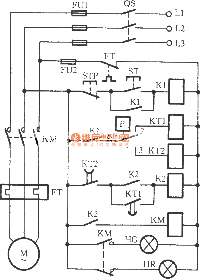
The circuit utilizes two time relays, KT1 and KT2, which are connected in series with the contacts of an electric contact pressure gauge (SP). This configuration helps to mitigate issues such as tremors or sparking that may occur due...
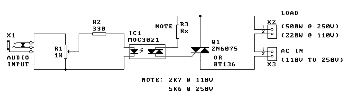
A music-to-light modulator is a circuit which controls the intensity of one or more lights in response to an audio input. The problem in older circuits is that there was a direct electrical connection between the lights using mains...
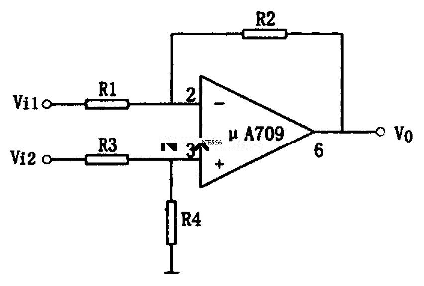
The simple differential amplifier circuit consists of two input signals, Vi1 and Vi2, which are connected through resistors R1, R3, and R4, forming a voltage divider circuit at the op-amp input. Vi1 is applied to the inverting input of...
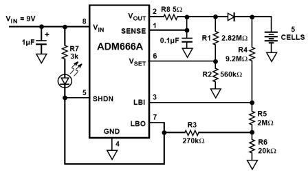
NiMH charger circuit diagram using ADM66A. Related searches include charger circuit, NiMH charger circuit, lead acid battery charger circuit, LiPo charger circuit, automatic battery charger circuit, simple battery charger circuit, lithium battery charger circuit, charger circuit diagram, and 12V...
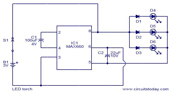
This circuit is a simple LED torch utilizing the MAX660 integrated circuit from MAXIM semiconductors. The MAX660 is a CMOS monolithic voltage converter IC capable of driving three bright white LEDs connected in parallel to output pin 8 of...
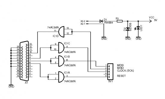
The brain of the robot is composed of an Atmel Tiny2313 microcontroller. This MCU features In-System Programming, allowing programming of its memory using a low-cost programmer. A simple programmer connects to the parallel port and is described in the...