
Ic Product Detectors

The described product detectors are essential components in radio frequency (RF) applications, particularly for receiving and demodulating SSB and CW signals. The use of integrated circuit devices allows for compact design and enhanced performance, making them suitable for various communication systems.
The operating frequency range of 20 to 30 MHz indicates that these detectors are intended for use in the high-frequency (HF) bands, commonly utilized in amateur radio and other communication systems. The ability to detect SSB signals is particularly important in these applications, as SSB is a widely used mode for voice communication in HF bands due to its efficient use of bandwidth.
The toroidal transformer T3, with its 1:1:1 winding ratio, serves a critical role in the circuit. This configuration is typically used to provide impedance matching and minimize losses in the signal path. The choice of a toroidal core helps to reduce electromagnetic interference (EMI) and improve overall performance by providing a high inductance in a compact form factor. The specific BFO frequency will determine the exact tuning and operational characteristics of the detector, allowing for precise signal demodulation.
In summary, these product detectors represent a sophisticated solution for detecting SSB and CW signals in the specified frequency range, utilizing IC technology and a carefully designed transformer to achieve optimal performance in RF applications. These product detectors use IC devices. SSB and CW signals can be detected with them. The circuits should be useful up to 20 or 30 MHz. T3 in (c) is a 1:1:1 toroidal type, depending on the BFO frequency.
Related Circuits
The following circuit illustrates an LM555 integrated circuit (IC) motion detector utilizing infrared sensors. Features include the generation of an infrared pulse modulation at 5 kHz, along with bandwidth control. The LM555 timer IC is a versatile component widely used...
The following circuit is an enhanced version of the original Lightning Detector designed to operate on a 5-volt supply. This updated circuit incorporates a refined RF section with a single resonance near 300 kHz and increased sensitivity. The use...
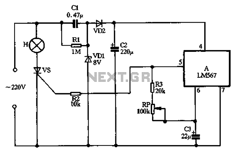
Cl, VDI, VD2, C2 form a simple capacitive step-down voltage regulator circuit with a rectifier output providing approximately 8V DC voltage for the LM567. A 5.6-foot manifold is connected. Resistors R3, RP, and capacitor C3 create an ultra-low frequency...
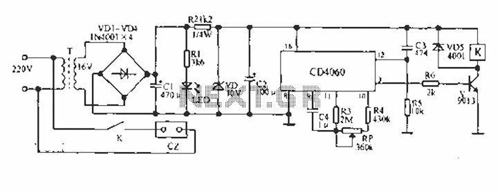
A CD4060 production time controller circuit is illustrated below. It is connected in such a way that R5 and C3 form a differential circuit to create a delay time from the start. Under the influence of the oscillating signal,...
The sensors used are silicon phototransistors and Cadmium Sulfide (CdS) photocells. Both of these sensors allow less current to flow when they are dark than when lighted. Phototransistors change their conductance while photocells change their resistance depending on the...
This circuit is a valuable tool that is easy to assemble and demonstrates greater sensitivity than many commercial devices. It utilizes an LF351 low-noise operational amplifier and a 1mF choke as the sensor. Unlike most basic EMF detectors, this...