
Visible and Infrared Light Detectors
The circuit employs silicon phototransistors and CdS photocells as primary light-sensing components. Silicon phototransistors operate based on light intensity, where their conductance increases with the presence of light, allowing more current to flow. Conversely, in darkness, their conductance decreases, limiting the current. On the other hand, CdS photocells exhibit a change in resistance based on light exposure; they have low resistance in bright light and high resistance in darkness.
In the schematic, the phototransistors and photocells are connected to the input terminals of either the LM339 or LM393 voltage comparator integrated circuits. These comparators are essential for monitoring the voltage changes across the sensors. When the sensors detect varying light levels, the change in voltage is fed into the comparator, which compares this voltage against a reference voltage set by a voltage divider network.
The output of the LM339 or LM393 can be used to drive additional circuitry, such as relays, LEDs, or microcontrollers, depending on the application. The choice between using the LM339 (quad comparator) or LM393 (dual comparator) depends on the number of sensors and the complexity of the desired circuit. The design ensures that the system can effectively respond to changes in ambient light conditions, making it suitable for applications such as automatic lighting systems, alarm systems, or light-sensitive control systems.
For optimal performance, it is important to consider the specifications of the selected sensors and comparators, including their response times and operating voltage ranges, to ensure compatibility and reliability in the intended application.The sensors used are silicon phototransistors and Cadmium Sulfide (CdS) photocells. Both of these sensors allow less current to flow when they are dark than when lighted. Phototransistors change their conductance while photocells change their resistance depending on the intensity of the light falling on them. All of the detectors on this page use LM339 Quad or LM393 dual voltage comparator integrated circuits to detect the change in voltage across the sensor.
For information on Voltage Comparators please see the Voltage Comparator Information page at this site. 🔗 External reference
Related Circuits
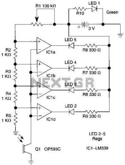
The outputs from the comparators will transition, in sequence, from high to low as the input voltage exceeds the reference voltage applied to each comparator. The output LEDs will activate sequentially as the voltage increases. The inverting inputs of...
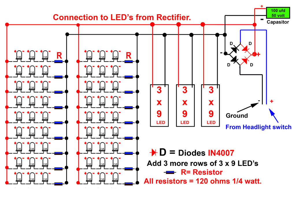
Gently bend the leads of the LEDs and, using the provided schematic circuit diagram, begin to solder. Once soldering is complete, it should... To successfully assemble the LED circuit, it is essential to follow a systematic approach. Start by preparing...
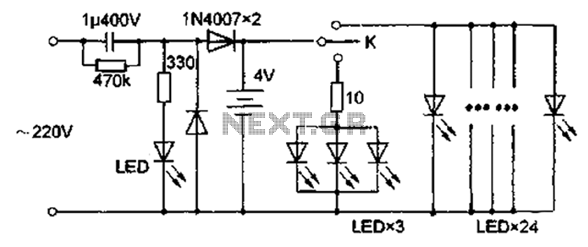
The circuit diagram depicted in Figure 5 illustrates a system for charging a lead-acid battery using 220V AC power. The circuit employs a capacitor, buck converter, and diode rectifier for this purpose. A red LED indicates the charging status....
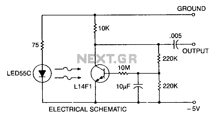
This self-biasing configuration is useful whenever small changes in light level must be detected, such as when monitoring very low flow rates by counting drops of fluid. In this bias method, the photodarlington is bias stabilized by feedback from...
To capture high-speed photographs, a fast shutter or light source is essential. This project involved examining a commercial flash unit to analyze its light profile. A phototransistor was connected in an emitter follower configuration with a low impedance emitter...
The circuit was originally available in kit form from a surplus supplier, but it is likely more widely accessible now. It introduces innovative concepts such as utilizing a 555 timer as a pulse width modulator (PWM) and employing serial/parallel...