
Ideal Car Battery Charger
Adjustment
After manufacturing, TR1 should be set to the null position, and the following adjustments should be made: 1) Without connecting the battery, check that both LEDs turn on. 2) Connect a car battery to the charger and verify that LD2 is off and that a current (normally between 2 to 4 A) flows to the battery. 3) Adjust TR1 until LD2 turns on and the charging current is cut off. 4) Reset TR1 to the null position and charge the battery using the hydrometer technique (if unavailable, utilize a battery in good condition). Carefully adjust TR1 so that LD2 begins to turn on as the charging current decreases to a few hundred mA. If TR1 is set correctly, during subsequent charges, LD2 will begin to flicker as the battery charges. Once the battery is fully charged, LD2 will turn on completely. No further adjustment of TR1 is necessary. Q1 is connected in line with the battery and can be triggered by the circuit R3, R4, and LD2. The voltage at the battery terminals is monitored by R2, C1, TR1, and D2, which activate Q2 when the terminal voltage exceeds the predetermined level set by TR1. When an uncharged battery is connected, the terminal voltage is low, causing Q2 to turn off and allowing Q1 to be triggered in each half cycle by R3, R4, and LD2. Q1 functions as a simple rectifier, charging the battery. If the terminal voltage rises above the threshold set by TR1, Q2 will deactivate Q1, halting the current supply to the battery and turning on LD2 to indicate that charging is complete. Q1 and the bridge rectifier GR1 should be mounted on a suitable heatsink to ensure adequate cooling. M1 is a 5A DC ammeter used to monitor the charging current. Optionally, a voltmeter can be connected in parallel with the battery, provided it has a high input resistance to avoid influencing the measurement.
Part List
R1 = 1K ohms
D1 = 1N4001
T1 = 220V/17V 4A Transformer
R2 = 1.2K ohms
D2 = 6.8V 0.5W zener
LD1 = Green LED
R3 = 470 ohms
TR1 = 4.7K ohms trimmer
LD2 = Red LED
R4 = 470 ohms
Q1 = BTY79 or similar 6A SCR
M1 = 0-5A DC Ampere meter
R5 = 10K ohms
Q2 = C106D SCR
S1 = 10A D/P On-Off Switch
C1 = 10uF 25V
GR1 = 50V 6A Bridge Rectifier
F = 5A FuseThe usual chargers of battery automotive, are simple and cheap appliances that charge continuously the battery, with a rythm of few amperes, for the time where the appliance is ON. If the holder do not close in time the charger, the battery will overcharge and her electrolytic faculty are lost with evaporation or likely exists destruction of her elements.
The charger of circuit exceeds these faults. It checks electronic the situation of charge of battery and it has circuit of control with retroaction, that forces the battery charge with biggest rythm until charge completely. When charge completely, it turns on one RED led (LD2). The charger has been drawn in order to charge batteries of 12V, ONLY. What should watch it from what it manufactures the circuit, they are the cables that connect the transformer with the circuit and in the continuity the battery, should they are big cross-section, so that heat when it passes from in them the current of charge and also they do not cause fall of voltage at the way of current through them. Adjustment When it finishes the manufacture you turn TR1 in the place of null price and you make the below regulations - controls.
1 ] You check without you have connected the battery, that also the two LED's turn on. 2 ] You connect a battery automotive in the charger. Check that the LD2 is off and that a current (normally 2 until 4 A), flows to the battery. 3 ] You turn the TR1 and you check that the LD2 can turn on, also the current of charge be cut 4 ] Turn the TR1 in the null price and charge the battery using the regular technique of hydrometer (if it does not exist, then you completely use a battery in good situation and charge). Turn carefully the TR1 so the LD2 begins to turn on also the current of charge to fall in few hundreds mA.
If the TR1 is placed rightly then in next charges, you will see the LD2 it will begin first to flicker, as charge the battery. When charge completely the battery then the LD2 turns on completely. The TR1 does not need anymore other regulation. The Q1 is connected in line with the circuit of battery and it can be fired from circuit R3-4 and LD2..
The voltage, on binding post of battery, is received by circuit R2, C1, TR1, D2 and it activates the Q2 when the voltage on binding post exceeds, the price that we have predetermined with the TR1. When a uncharged battery is placed for charge, the voltage on binding post, is low. Under this situation the Q2 is turn off and Q1 is fired in each half of circle from circuit R3-4, LD2.
The Q1 functions as simple rectifier. As such charge the battery, the voltage on binding post increases. If the voltage on binding post is increased above the level that we have fixed with the TR1, then the Q2 it shifts the control of gate of Q1, this deactivate, stops it gives current in the battery and it turns on LD2, showing us that the charge has been completed. The Q1 and the bridge of rectification GR1, it should install on good heatsink, for good refrigeration.
The M1 is a ampere meter 5A DC, in order to we can watch the current of charge. Optionally it can be placed a voltmeter in parallel, with the poles of battery, will be supposed it has however high resistance of entry, in order to it does not influence the circuit of measurement of appliance. After assembling of the circuit, adjust TR1 to null value, power-up and make the following adjustments :- [1] Without connecting the battery check that the 2 LED?s are turned on.
[2] Connect a car battery to the circuit and check that LD2 is OFF and a current (normally 2A to 4A) is flowing to the battery. [3] Adjust TR1 until LD2 turns ON and the charge current is cut. [4] Adjust TR1 to null value and charge the battery using the hydrometer technique (if you do not have or do not know how to use a hydrometer, then use a good condition battery and charge).
Carefully adjust TR1 so that LD2 begins to turn ON and the charge current falls to a few hundred milliamps (mA). If TR1 is set correctly then in the next round of charging you will noticed LD2 begin to flicker as the battery is being charged.
When battery is completely charged, LD2 turns ON completely.TR1 does not need further adjustment anymore. Q1 is connected in line with the battery and is fired by R3, R4 and LD2. The R2, C1, TR1 and D2 sense the voltage of the battery terminal and activate Q2 when the voltage of the battery terminal exceeds the value predetermined by TR1.
When an uncharged battery is connected, the terminal voltage is low. Under this circumstance, Q2 is turned OFF and Q1 is fired in each half cycle by R3, R4 and LD2. The Q1 functions as a simple rectifier and charges the battery. If the battery terminal voltage is increased above the level that had been fixed by TR1, then Q2 shifts the control of Q1 gate. This deactivates Q1 and cuts off the current supply to the battery and turns LD2 ON indicating that the charge has been completed.
Q1 and bridge rectifier GR1 should be mounted on heatsinks to prevent overheating. M1 is a 5A DC ammeter to measure the charge current. Optionally a voltmeter can be connected in parallel with the battery, however it must have a high input resistance so as not to influence the measurement. Part List R1= 1Kohms D1= 1N4001 T1= 220V/17V 4A Transformer R2= 1.2Kohms D2= 6.8V 0.5W zener LD1= Green LED R3= 470 ohms TR1= 4.7Kohms trimmer LD2= Red LED R4= 470 ohms Q1= BTY79 or similar 6A SCR M1= 0-5A DC Ampere meter R5= 10Kohms Q2= C106D SCR S1= 10A D/P On ?
Off Switch C1= 10uF 25V GR1= 50V 6A Bridge Rectifier F= 5A Fuse 🔗 External reference
Related Circuits
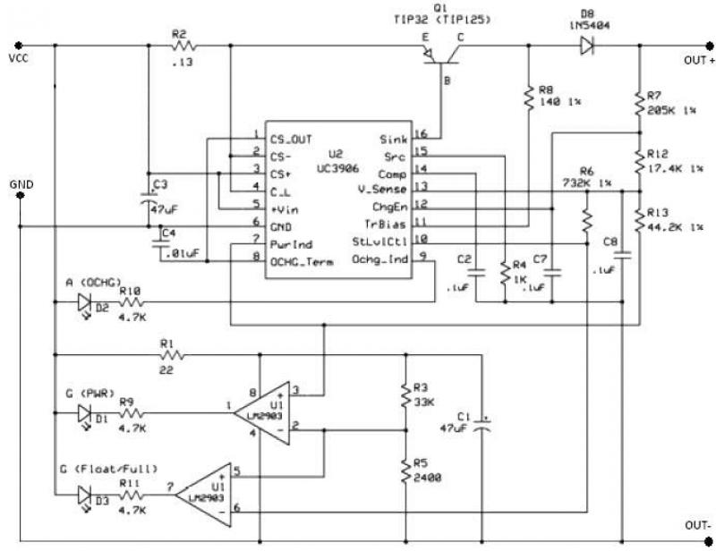
The UC3906 battery charger circuit controller includes all necessary circuitry to manage the charge and hold cycles for sealed lead-acid batteries. This circuit is specifically designed to deliver the appropriate charging voltage and current based on the battery's temperature...
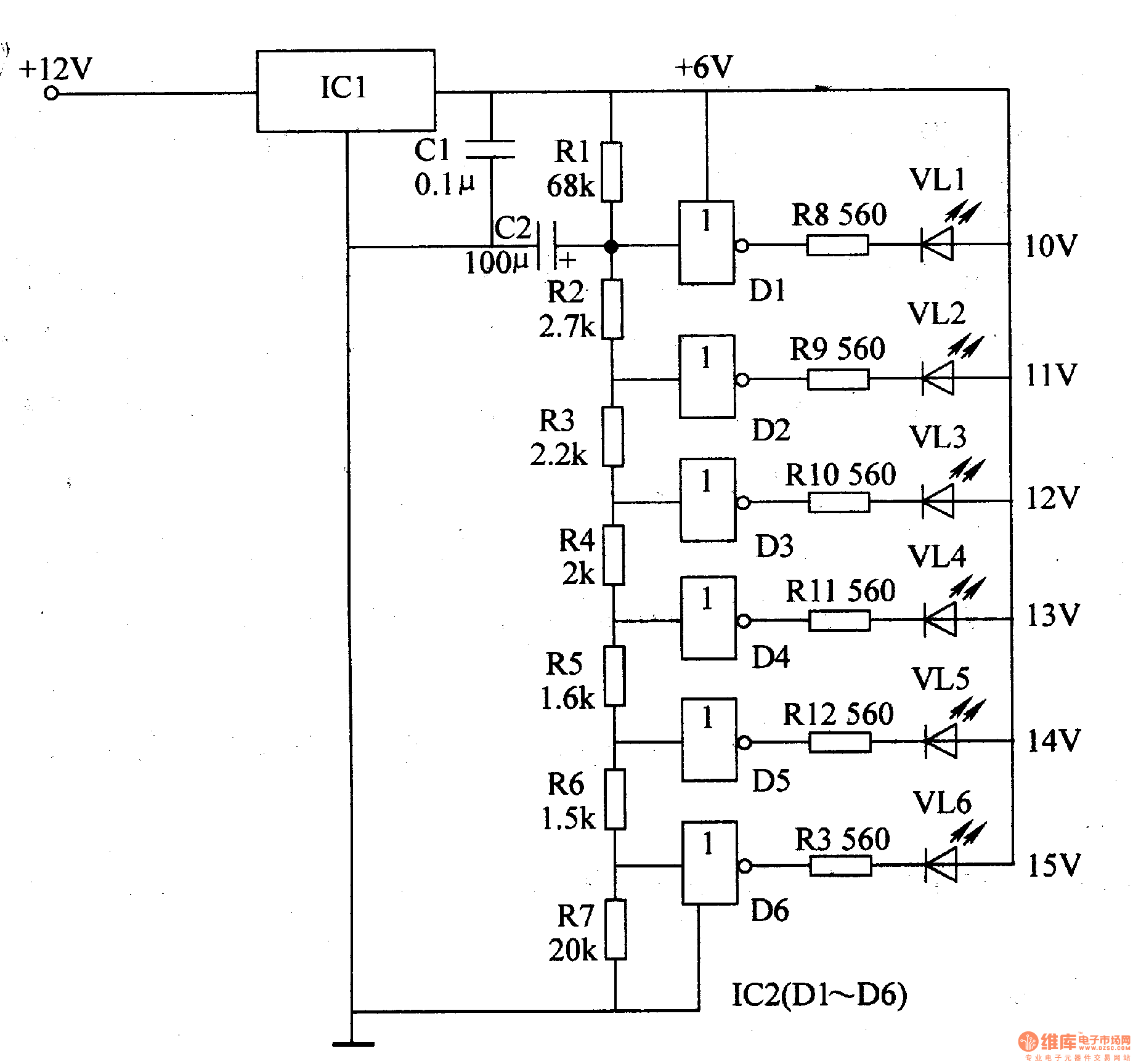
The LED car voltmeter comprises a filter circuit, a voltage distribution filter circuit, a voltage amplifier circuit, and an LED display circuit, as illustrated in Figure 7-77. The regulator filter circuit includes a 3-terminal IC (IC1) and a filter...
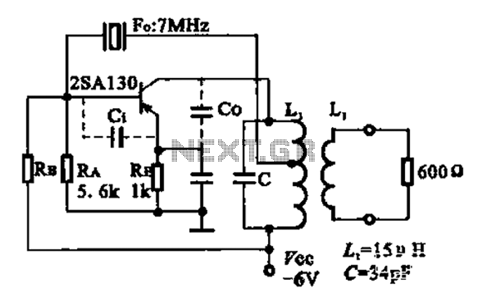
The 2SA130 transistor is used in an oscillator circuit with an oscillation frequency of 7 MHz. The power supply voltage is 6V, and the load is a frequency-selective resonant circuit with a quality factor of 600. The circuit utilizes the...
The charger in this project is designed to charge two AA NiMH or NiCd cells of any capacity (as long as they are the same) at approximately 470mA. It will charge 700mAh NiCds in about 1.5 hours, 1500mAh NiMHs...
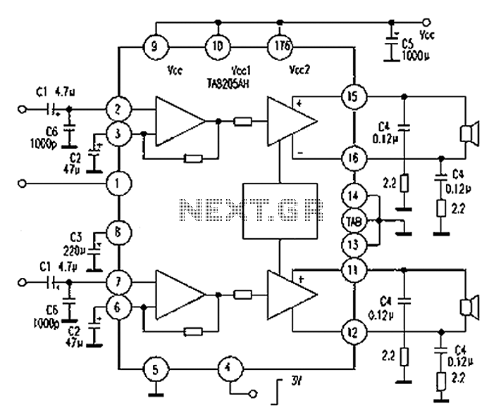
A Mitsubishi Pajero car audio system is experiencing a silent fault, while other features remain operational. The issue is traced to a damaged amplifier IC, specifically the TA8205AH. This integrated circuit, produced by Toshiba, is a dual-channel audio power...
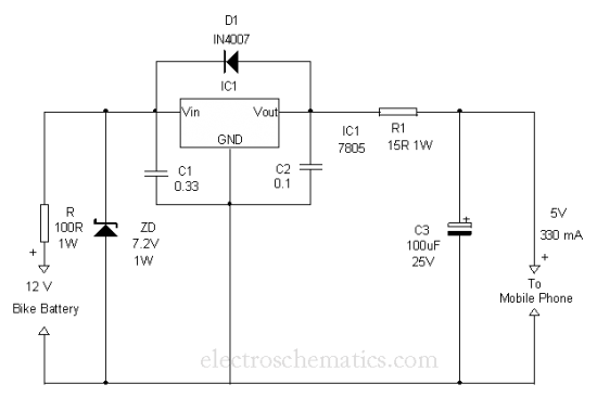
This is a simple and easy method to extract current from a motorcycle battery to charge a mobile phone. Most mobile phone battery packs consist of three 1.2 V cells. To effectively tap current from a motorcycle battery for mobile...
Warning: include(partials/cookie-banner.php): Failed to open stream: Permission denied in /var/www/html/nextgr/view-circuit.php on line 713
Warning: include(): Failed opening 'partials/cookie-banner.php' for inclusion (include_path='.:/usr/share/php') in /var/www/html/nextgr/view-circuit.php on line 713