
The LED car voltmeter (3)
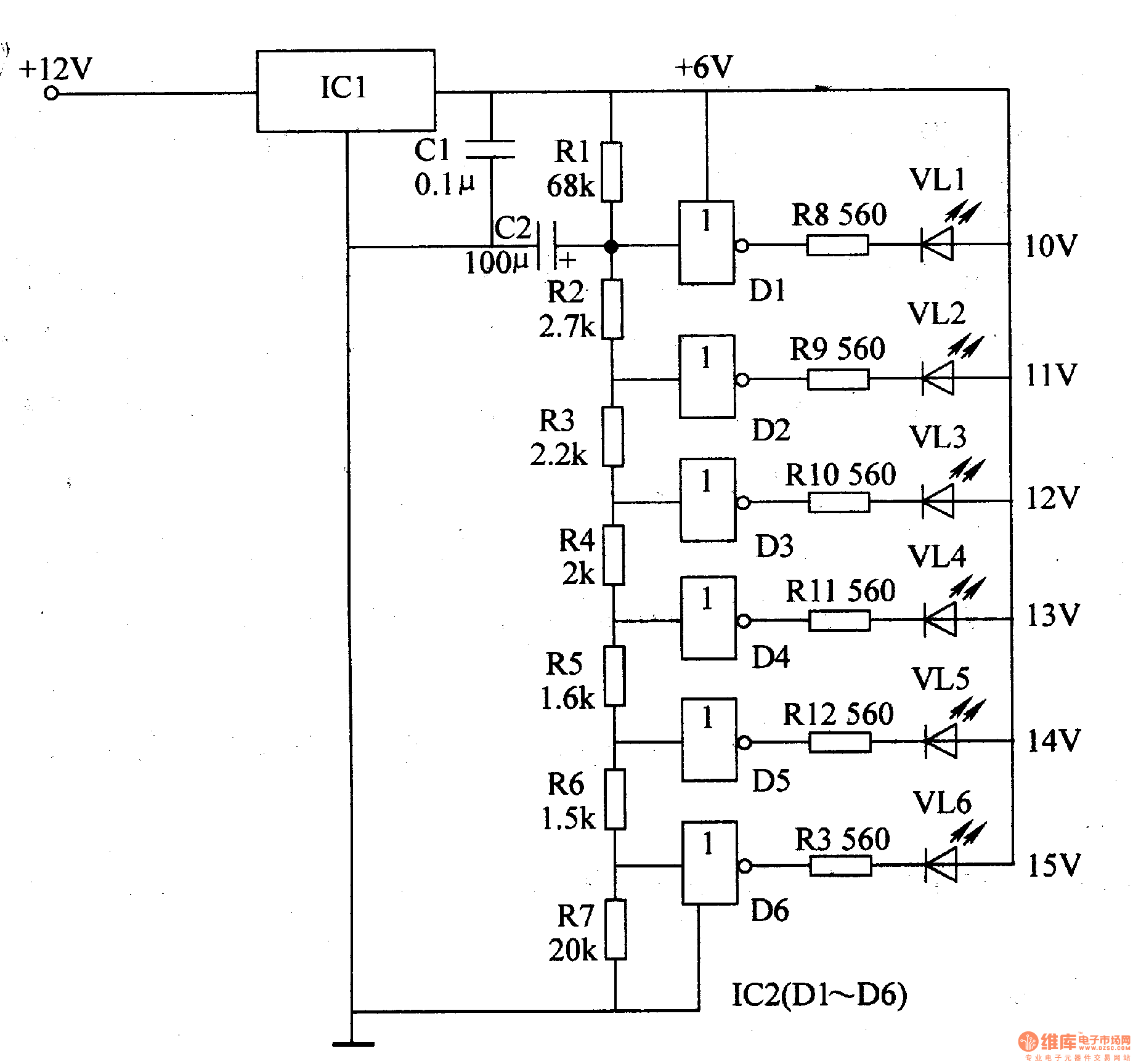
The LED car voltmeter is an essential device for monitoring the voltage levels in automotive applications. The filter circuit plays a crucial role in stabilizing the input voltage by using a 3-terminal voltage regulator (IC1). This regulator ensures a consistent output voltage regardless of input fluctuations, which is essential for accurate voltage measurement. The filter capacitor (C1) is connected to the output of the regulator to smooth any remaining ripples in the voltage signal, thereby enhancing the performance of the voltmeter.
Following the regulator, the voltage distribution filter circuit is designed to divide the voltage levels appropriately for further processing. This circuit consists of multiple resistors (R1-R7) that create a voltage divider network, allowing specific voltage levels to be tapped for amplification. Capacitor (C2) is included in this circuit to filter out high-frequency noise, ensuring that only stable voltage levels are passed to the next stage.
The voltage amplifier circuit utilizes a 6 NOR gate configuration (IC2) to amplify the voltage signals received from the voltage distribution filter circuit. NOR gates are used in this application due to their ability to perform logical operations while also serving as amplifiers. The outputs of the NOR gates (D1-D6) provide a stronger voltage signal that is suitable for driving the LED display circuit.
Finally, the LED display circuit consists of six LEDs (V1-V6) that visually represent the voltage levels. Each LED is paired with a resistor (R8-R13) to limit the current flowing through the LEDs, preventing damage and ensuring longevity. The combination of these components allows the voltmeter to provide real-time voltage readings in a clear and understandable format, making it easier for users to monitor their vehicle's electrical system. Overall, the design of the LED car voltmeter integrates various electronic components to achieve accurate voltage measurement and display functionality.The LED car voltmeter consists of the filter circuit, voltage distribution filter circuit, voltage amplifier circuit and LED display circuit, see as figure 7-77. The regulator filter circuit consists of the 3-terminal IC1 and filter capacitor C1. The voltage distribution filter circuit consists of the resistors R1-R7 and capacitor C2. The voltage amplifier circuit consists of the 6 NOR gate circuitS IC2 (D1-D6). The LED display circuit consists of the LED vl1-vl6 and resistors R8-R13. 🔗 External reference
Related Circuits
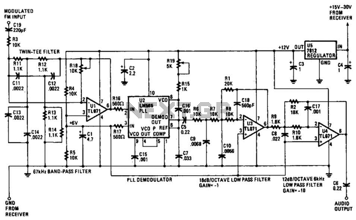
The operational amplifier (Op Amp) U1 and its associated components form a 67-kHz bandpass filter. A twin-T network, consisting of four 1100-ohm resistors and four 0.0022-microfarad capacitors, is integrated into the feedback loop of the op amp. This configuration...
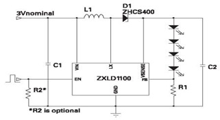
The ZXLD1100 is a PFM flyback DC to DC boost converter that operates in discontinuous mode. The following circuit diagram illustrates the configuration of four LED drivers for handset LCD backlighting using this device. The ZXLD1100 is designed to...
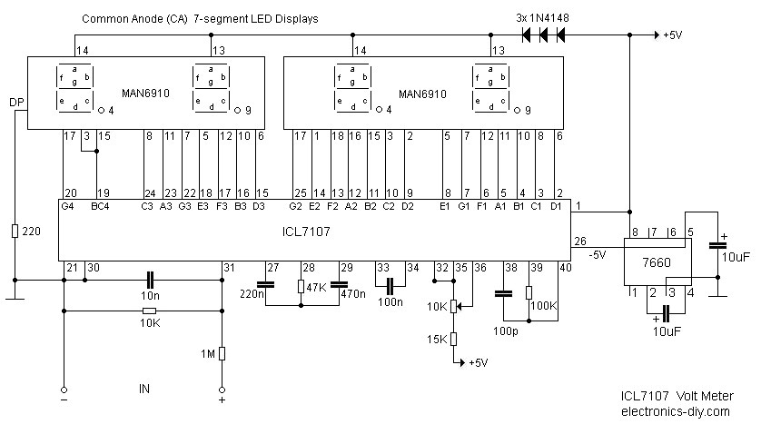
This digital voltmeter is ideal for measuring the output voltage of a DC power supply. It features a 3.5-digit LED display with a negative voltage indicator. The device measures DC voltages from 0 to 199.9V with a resolution of...
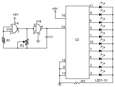
This schematic represents a version of a simple LED chaser. A 555 timer is not utilized due to its high cost at local electronics stores, which is over $4 CAD. Instead, an oscillator is constructed using two sections of...
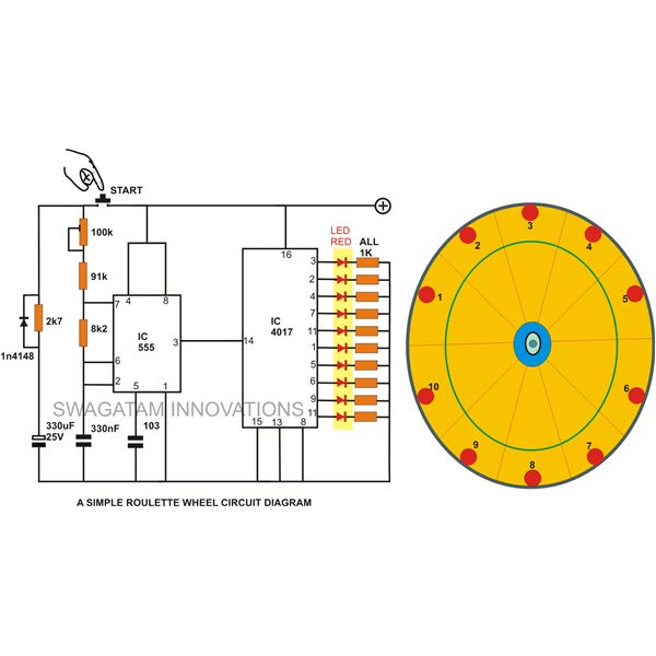
A simple circuit for a 10 LED roulette wheel is presented. Pressing the button initiates the LEDs in a rotational sequence that starts at full speed and gradually decelerates until it halts at a randomly selected LED. The randomness...
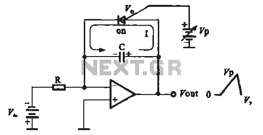
A sawtooth voltage-controlled oscillator operates by first generating a negative potential maximum at the output of the comparator. This output is then fed to the inverting input terminal through resistor R1, which is part of the relaxation oscillator. The...
Warning: include(partials/cookie-banner.php): Failed to open stream: Permission denied in /var/www/html/nextgr/view-circuit.php on line 713
Warning: include(): Failed opening 'partials/cookie-banner.php' for inclusion (include_path='.:/usr/share/php') in /var/www/html/nextgr/view-circuit.php on line 713