
UC3906 battery charger controller circuit
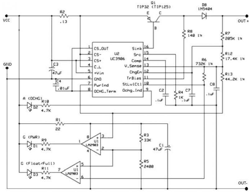
The UC3906 features separate voltage loop and current limit amplifiers that adjust the output voltage and current levels in the charger by controlling the onboard driver. The circuit requires a DC input voltage ranging from 18 to 22 volts. Three optical LED indicators display the charge state. The IC is configured to provide three charge states: Bulk charge, where the charger operates in a constant-current mode until the battery reaches the programmed full-charge voltage; Overcharge, where the charger switches to overcharge mode to ‘top-off’ the battery once the full-charge voltage is reached; and Float charge, which occurs when the current decreases to the minimum overcharge current, signaling the charger to enter float charge mode.
The UC3906 battery charger circuit is an efficient solution for managing the charging process of sealed lead-acid batteries. The integration of separate voltage and current control loops allows for precise regulation of the output parameters, ensuring optimal charging conditions. The necessity for a DC input voltage of 18 to 22 volts is critical, as it provides the required headroom for the charging process.
The three charge states are designed to accommodate the various stages of battery charging, enhancing battery longevity and performance. During the Bulk charge phase, the constant-current mode allows for rapid charging until the target voltage is achieved. Transitioning to the Overcharge state prevents the battery from becoming undercharged by providing a slight additional charge to ensure full capacity. Finally, the Float charge mode maintains the battery's charge without overloading it, which is crucial for long-term storage and usage.
The use of optical LED indicators not only enhances user interface but also provides real-time feedback on the charging status, allowing users to monitor the charging process easily. This comprehensive approach to battery management ensures that the UC3906 charger circuit can effectively extend the life of sealed lead-acid batteries while maintaining safety and efficiency throughout the charging cycle.This UC3906 battery charger circuit controller contains all of the necessary circuitry to control the charge and hold cycle for sealed lead-acid batteries. The UC3906 battery charger circuit is specifically designed to provide the proper charging voltage and current determined by the temperature and state of charge of the battery.
The UC3906 battery charger circuit controller monitor and control both the output voltage and current of the charger through three separate charge states . UC3906 has separate voltage loop and current limit amplifiers which regulate the output voltage and current levels in the charger by controlling the onboard driver.The charger circuit requires 18 to 22 volts DC input. Three optical ( LED ) indicators show the charge state . This IC is configured to provide three charge states: Bulk charge – the charger operates in a constant-current charge mode until the battery reaches the programmed full-charge voltage.
Overcharge – when the voltage reaches the programmed full-charge voltage, the charger switches to overcharge mode to ‘top-off’ the battery. Float charge – when the current decreases to the minimum overcharge current, the charger enters the float charge mode.
🔗 External reference
Related Circuits
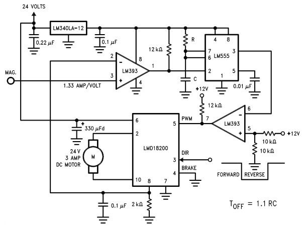
The LMD18200 3A H-Bridge, designed by National Semiconductors, can be used to create a simple motor controller electronic project suitable for motion control applications. This component is ideal for driving both DC and stepper motors, accommodating peak output currents...
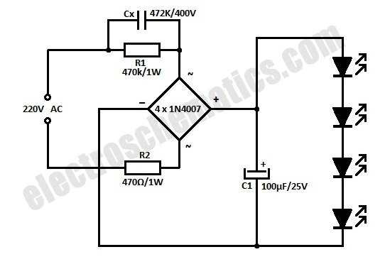
This is a simplified version of a white LED lamp that can be powered directly from the mains. It provides sufficient illumination for reading purposes. Capacitor Cx along... The circuit for the white LED lamp consists of several key components...

A simple transistor amplifier circuit diagram and schematic that can be used as a 12-watt audio transistor amplifier. An operational amplifier (op-amp) integrated circuit (IC) is used to produce the required gain. This circuit is designed to amplify audio signals,...
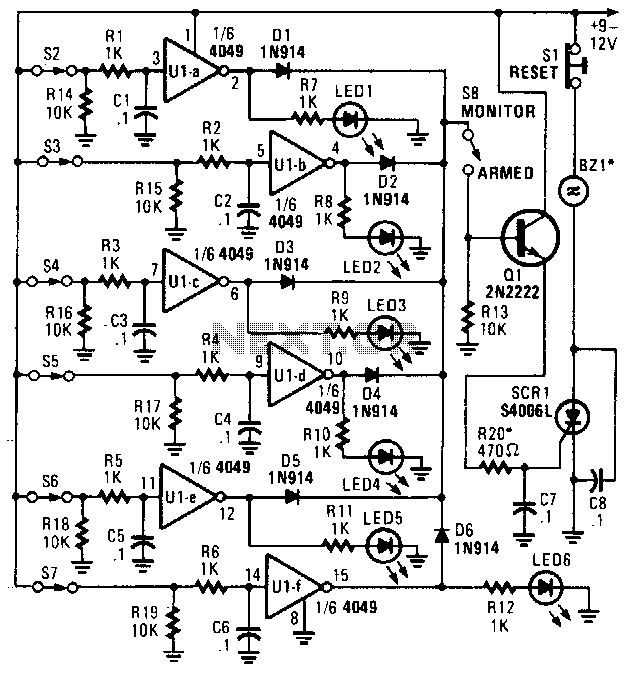
This alarm features status LEDs connected to each inverter output, which indicate the status of the corresponding sensor. S8 is utilized to monitor the switches through the LEDs or to activate an alarm using Q1 and SCR1. Additionally, BZ1...
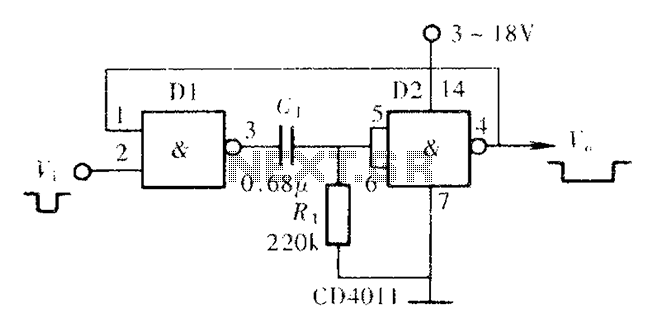
A CMOS NAND gate or NOR gate can form a monostable multivibrator, commonly referred to as a single-shot. This circuit is extensively used to delay pulse signals, allowing for signal stretching and shaping. The main principle involves utilizing the...
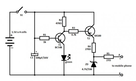
This is an ideal mobile charger that utilizes 1.5-volt pen cells to charge mobile phones while traveling. It can replenish a cell phone battery three or four times. The mobile charger circuit is designed to be compact and portable, making...
Warning: include(partials/cookie-banner.php): Failed to open stream: Permission denied in /var/www/html/nextgr/view-circuit.php on line 713
Warning: include(): Failed opening 'partials/cookie-banner.php' for inclusion (include_path='.:/usr/share/php') in /var/www/html/nextgr/view-circuit.php on line 713