
Automatic Loudness Control circuit
The proposed circuit design incorporates an automatic tone control mechanism within the preamplifier stage of an audio system. This circuit utilizes a combination of operational amplifiers, resistors, capacitors, and a microcontroller or potentiometer for real-time adjustments. The operational amplifiers serve as the core components for signal amplification and filtering, allowing for precise manipulation of the audio signal.
The frequency response adjustment is achieved by utilizing a variable resistor or digital potentiometer connected to the control knob. As the user adjusts the knob, the microcontroller interprets the position and alters the gain and frequency response characteristics accordingly. This is done by dynamically changing the values of the resistors and capacitors in the feedback loop of the op-amps, effectively shaping the audio signal to compensate for the varying sensitivity of the human ear across different frequencies.
Incorporating feedback from the Fletcher-Munson curves into the design allows the circuit to tailor the audio output to ensure that frequencies perceived as less sensitive at lower volume levels are boosted, while those perceived as more sensitive are attenuated. This results in a balanced audio output that remains consistent regardless of the listening level.
The circuit layout should include power supply decoupling to minimize noise, ensuring high fidelity in audio reproduction. Additionally, careful consideration of component selection is crucial to maintain the integrity of the audio signal throughout the processing stages. The overall design facilitates a seamless integration into existing audio systems, enhancing the listening experience by providing a more responsive and adaptive audio output tailored to the listener's preferences.In order to obtain a good audio reproduction at different listening levels, a different tone-controls setting should be necessary to suit the well known behaviour of the human ear. In fact, the human ear sensitivity varies in a non-linear manner through the entire audible frequency band, as shown by Fletcher-Munson curves.
A simple approach to this problem can be done inserting a circuit in the preamplifier stage, capable of varying automatically the frequency response of the entire audio chain in respect to the position of the control knob, in order to keep ideal listening conditions under different listening levels.. 🔗 External reference
Related Circuits
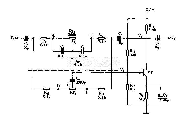
The circuit is a decay feedback tone control circuit that incorporates anti-attenuation feedback action. Its primary function is to enhance or attenuate bass frequencies, although this distinction can sometimes be challenging to perceive. The analysis utilizes the superposition theorem,...
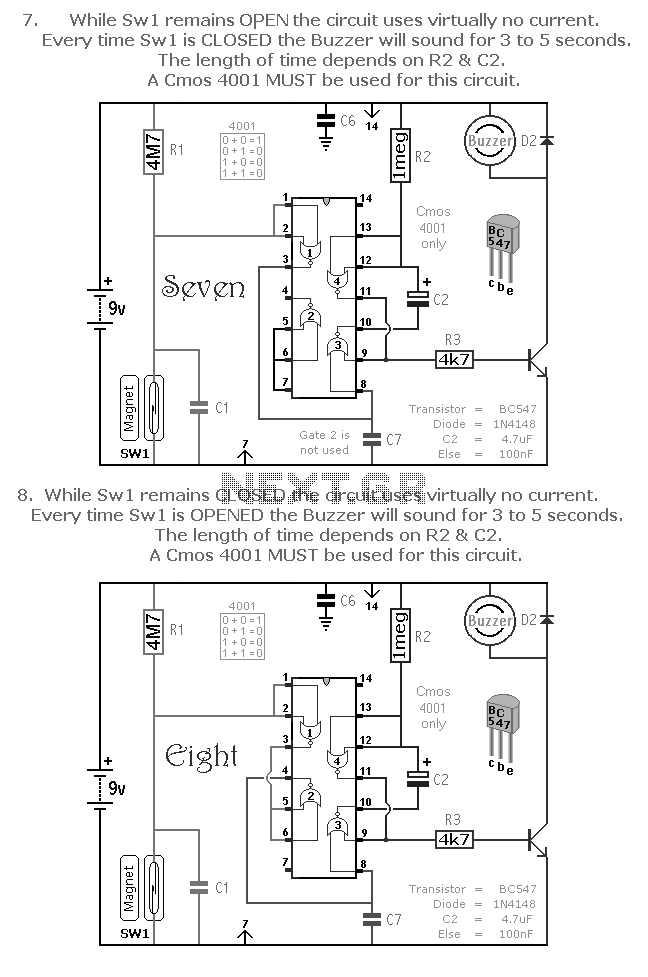
A selection of small self-contained CMOS alarm circuits is presented. The main features of each alarm are indicated on the circuit diagram itself. All circuits exhibit a very low standby current, making them suitable for battery operation. Each pair...
A large mirror is installed on the left wall, enhancing the brightness of the room. However, when watching movies, a dark environment is preferred, as reflections of the film appear in the mirror, which can be distracting. To address...
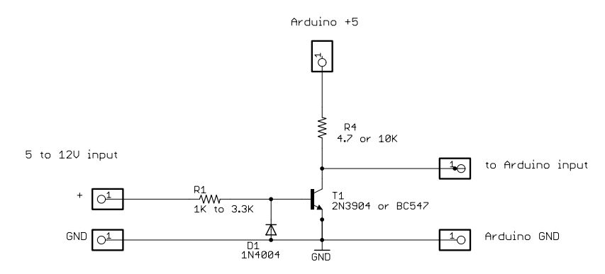
The principles of DC motors are discussed in the beginner and intermediate sections of this tutorial. This section will address the electronics required to interface them with a Basic X microcontroller or other digital chips. The simplest method of...
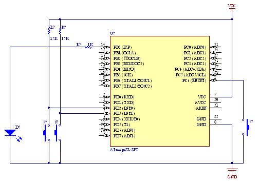
A demonstration of external interrupts in the AVR (Atmega8) microcontroller, including a circuit diagram and C code for the interrupt service routine (ISR). The Atmega8 microcontroller is a versatile device widely used in embedded systems, particularly for applications requiring external...
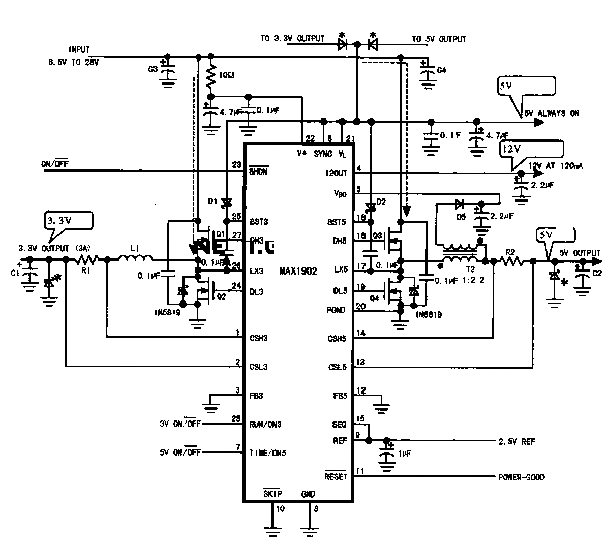
Multi-output power supply circuit (MAX1902). This circuit illustrates the power supply configuration for a notebook computer motherboard, utilizing the MAX1902 chip for power control. It is designed to convert the battery's DC voltage into multiple DC voltage outputs. The multi-output...
Warning: include(partials/cookie-banner.php): Failed to open stream: Permission denied in /var/www/html/nextgr/view-circuit.php on line 713
Warning: include(): Failed opening 'partials/cookie-banner.php' for inclusion (include_path='.:/usr/share/php') in /var/www/html/nextgr/view-circuit.php on line 713