
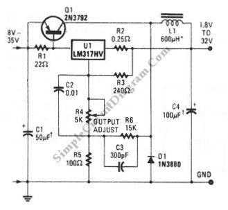
LM317 Voltage Regulator
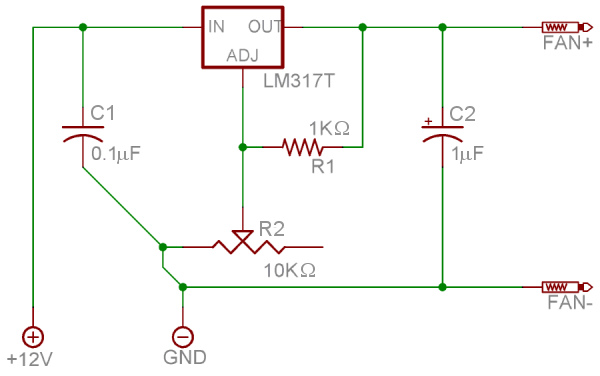
A 1KΩ resistor is recommended, which will carry no more than 100 microamps, allowing for a smaller wattage rating of 1/8 watt, though 1/4 watt is suggested. A 0.1µF ceramic capacitor should be placed across the incoming power leads to smooth out ripples before they reach the regulator. Additionally, a 1µF polarized aluminum or tantalum capacitor should be connected across the output leads to provide a buffer effect during output voltage adjustments. Larger capacitors can be used for increased buffering, but values over 10µF may be excessive. Heatsink compound is essential for proper thermal management, and a 10KΩ potentiometer or rheostat will serve as the output voltage adjustment knob. The output voltage of the LM317 is determined by the formula V_out = 1.25V x (1 + R2/R1), where R2 is the potentiometer and R1 is the fixed resistor. For a 12V input, a 10KΩ potentiometer and a 1KΩ resistor will yield an output voltage range of 1.25V to 11.5V.
To assemble the circuit, apply a thin layer of heatsink paste to the back of the regulator, ensuring proper contact with the heatsink. The heatsink should then be securely attached to prevent bending or detaching from the regulator. It is critical to avoid grounding the heatsink, as the tab is connected to the output voltage pin, which could lead to catastrophic failure of the power supply. Proper mounting and support of the heatsink are essential for reliable operation.The LM317T is an extremely common positive voltage regulator - many laboratory supplies and other equipment are based on it. It can produce any amount between 1. 25V and up to 35V by adjusting the resistance (opposition to current) between its adjustment pin and ground.
Secondly, and this is IMPORTANT, the LM317T is a linear regulator. This means t hat it dissipates the excess voltage as heat, with more heat produced as the voltage is set lower and lower. You MUST have a heatsink mounted on the regulator that is capable of dissipating the heat produced. Most fans give their total output in watts - if they give it in amps, multiply that by 12. Your heatsink MUST be capable of dissipating the total wattage of all fans on the regulator safely. Heatsinks can get BIG at the upper wattages. (Be careful with published heatsink ratings; most sinks will say they dissipate 5W, but will heat up to 20 or 30 degrees above ambient at that wattage.
) Here`s one last thing to keep in mind; fans pull more amperage when they`re run at a lower voltage, on account of having less torque. For example, a Panaflo 120mm H1A pulls 0. 6 A at full 12V. However, at 6V, it pulls closer to 0. 85 A. You need to account for the highest possible current draw (usually occurs at 6V) from each fan connected to the regulator, and make sure you keep under the 1.
5A limit. If you need more than 1. 5A of current, and have a heatsink large enough to handle the wattage (old stereos and amplifiers are great for finding massive heatsinks, btw), you can use an LM350, which is rated up to 3 A and is identical to the LM317 in all other respects. The LM338 is also compatible, and is rated up to 5 A. The regulator itself. LM317/350/338s come in a variety of packaging; I suggest using the TO-220 package, it`s the most common.
(You may also find the TO-3 can package, which is much larger and heavier and has a different pinout, but dissipates heat better). A 1K © (kiloohm) resistor. This will never have more than 100 microamps going through it, as such you can safely get this as small as 1/8 watt.
However, I suggest 1/4 watt. A 0. 1 F (microfarad, sometimes also called MFD) ceramic capacitor. This will go across the incoming power leads and smooth out any ripples before it enters the regulator. You can also use mica, monolithic, or any other kind of unpolarized capacitor. A 1 F polarized aluminum or tantalum capacitor. This will go across the output leads, and give you a smooth buffer effect when you adjust the output.
You can use larger capacitors if you want a larger buffer, although anything over 10 uF is probably overkill. Heatsink paste/compound - this is a REQUIREMENT, just like a CPU. I`m using cheap zinc silicone stuff here, but if you have leftover Arctic Silver from your CPU or other paste, that`s fine.
A 10K © potentiometer or rheostat - this will be the knob for adjusting the output voltage. Again, you can safely go down to 1/8 watt here, but I suggest 1/4 watt. Once assembled, the output voltage of the LM317 is equal to 1. 25V x (1 + R2/R1). Since we`re feeding it 12V, a R2 (potentiometer) of 10K and an R1 (resistor) of 1K will give us the full possible range of the LM317 (minimum of 1. 25V, maximum of 11. 5V). First off, grease up the back of the regulator. It`s pretty similar to greasing a CPU - put on enough to fill up cracks between the heatsink and regulator, a tiny tiny bit of squeeze-out is fine, but don`t go overkill.
Then, screw on or clip on the heatsink, and solder it to the board. If your heatsink has pins to solder to the PCB, make sure you use those; you should somehow try to make sure the heatsink is properly supported and doesn`t bend or rip out the regulator. Caveat: The tab is connected to the output voltage pin. DON`T ground the heatsink, unless you enjoy watching a PSU emit blue smoke and/or a regulator crack in half/explode/catch on fire.
Mount it directly in front of the regulator. 🔗 External reference
Related Circuits
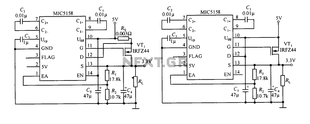
The circuit consists of peripheral components for the MIC5158, a linear regulator that converts a 5V input into a 3.3V output with a maximum current of 10A. When the input voltage (Ui) is 5V, an N-channel MOSFET, specifically the...
In this circuit, an LM339 quad voltage comparator is utilized to generate a time delay and control a high current output at low voltage. Approximately 5 amps of current can be sourced using a pair of fresh alkaline D...
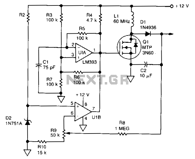
U1 is a dual voltage comparator with open collector outputs. The A side functions as an oscillator operating at 100 kHz, while the B side is part of the regulation circuit that compares a fraction of the output voltage...
A switching voltage regulator circuit depicted in the schematic diagram can serve as a cost-effective solution for high-efficiency electronic circuit requirements. The switching voltage regulator circuit operates by converting a higher input voltage to a lower output voltage with minimal...
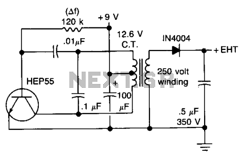
This circuit will generate approximately 300 volts DC at a very low current, sufficient for a GM tube. Caution is advised with the output. The described circuit is a high-voltage DC power supply designed to provide approximately 300 volts, which...
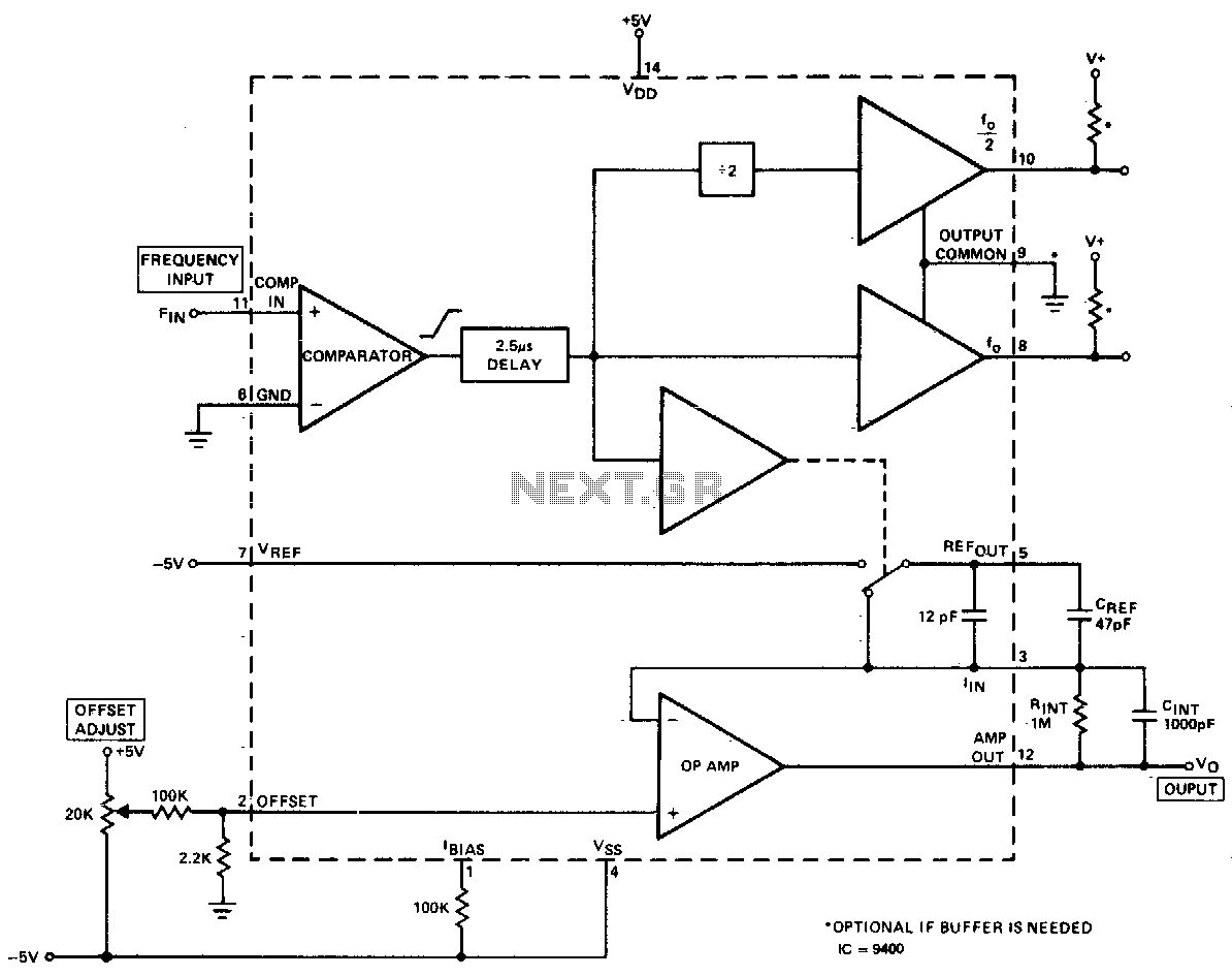
The converter produces an output voltage that is linearly proportional to the input frequency waveform. Each zero crossing at the comparator's input results in a specific amount of charge being dispensed into the op-amp's summing junction. This charge subsequently...