
USB Powered Stereo Computer Speaker
The USB-powered computer speaker circuit is designed to provide an efficient and compact audio amplification solution suitable for personal computers. The use of the TDA2822M integrated circuit allows for a simplified design that minimizes component count while maximizing performance. The low quiescent current and low crossover distortion characteristics of the TDA2822M enhance audio fidelity, making it a favorable choice for multimedia applications.
The circuit's power supply is derived from the USB port, ensuring compatibility with most modern computers. The inclusion of a power switch (S1) allows users to easily control the power state of the speakers, while the power indicator LED (LED1) provides a visual indication of the operational status.
The audio input stage employs capacitive coupling (C2 and C3) to block any DC components from the audio signals, ensuring that only the AC audio signal is amplified. The resistors (R2 and R3) provide the necessary impedance matching for the input signals. The volume control potentiometers (VR1 and VR2) allow for independent adjustment of the left and right audio channels, providing users with a customizable listening experience.
The Zobel network formed by R5 and C8, and R6 and C10 is crucial for maintaining stability in the audio amplifier circuit, particularly at higher frequencies. This network helps to dampen potential resonances and reduce distortion, contributing to a cleaner audio output.
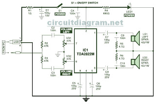
Overall, this USB-powered speaker circuit is a robust solution for enhancing audio output from computers, combining efficiency, ease of use, and high-quality sound reproduction in a compact package. Proper assembly on a general-purpose PCB and careful consideration of external connections will further enhance the performance and reliability of the system.This is the circuit diagram of USB powered computer speaker, or it widely known as multimedia speakers for PCs. The circuit has single-chipbased design, low-voltage electrical power supply, compatibility with USB power from computer, simple heat-sinking, inexpensive, large flexibility and wide temperature tolerance.
At the heart of the circuit is IC TDA2822M. This IC is, actually, monolithic type in 8-lead mini DIP (Dual Inline Package). It`s designed for use as a dual audio power amplifier in battery powered sound players. Features of TDA2822M are very low quiescent current, low crossover distortion, DC source voltage down to 1. 8 volts and minimal output power of approximately 450 mW/channel with 4 ohm loudspeaker at 5V DC supply input.
An ideal power amplifier can be basically described as a circuit which can supply audio power into external loads without having producing substantial signal distortion and without having consuming extreme quiescent current. This circuit is powered by 5V DC source obtainable from the USB port of the Computer. When electrical power switch S1 is turned to on` position, 5V power supply is extended towards the circuit and power indicator red LED1 illuminates immediately.
Resistor R1 is actually a current surge limiter and capacitors C1 and C4 work as buffers. The operation of the circuit is very simple. Audio signals from the Computer audio port or headphone port are fed towards the amplifier circuit via R2 and C2 (for left channel), and R3 and C3 ( forright channel). Potensiometer VR1 used as the volume controller for left (L) channel, while potensiometer VR2 used to control the volume level of right (R) channel.
Pin 7 of TDA2822M receives the left channel sound signals and pin 6 receives the right channel signals by way of VR1 and VR2, correspondingly. Amplified signals for driving the left and right loudspeakers can be obtained at pins 1 and pin 3 of IC1, correspondingly.
Components R5 and C8, and R6 and C10 form the classic zobel network. Construct the circuit on a medium size, general purpose PCB and enclose inside a appropriate case. It really is recommended to utilize a socket for IC TDA2822M. The external connections ought to be made working with suitably screened wires for improved result. 🔗 External reference
Related Circuits
The MAX5953A offers a straightforward, cost-effective, and comprehensive non-isolated power integrated circuit (IC) solution for Powered Devices (PD) in Power-over-Ethernet (PoE) systems. The MAX5953A is designed to facilitate the implementation of Power-over-Ethernet applications by providing an efficient means of...
This project is designed to charge a pair of AA Nickel Metal Hydride (NiMH) or Nickel Cadmium (NiCd) cells using a laptop's USB port for power. It addresses the need for a convenient charging solution. Any USB port can...
The high durability of a light-emitting diode (LED) makes it suitable for ON/OFF indicator applications. However, there are limitations regarding low operating voltage. Light-emitting diodes (LEDs) are semiconductor devices that emit light when an electric current passes through them. Their...
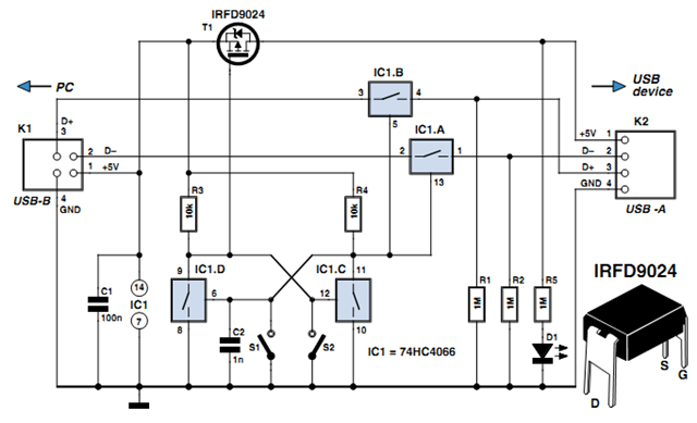
Individuals engaged in the experimentation or development of USB-connected peripheral hardware often find it frustrating to repeatedly disconnect and reconnect the plug to reestablish communication with the PC. This procedure is necessary, for instance, every time the peripheral device...
A 2 x 18W Hi-Fi Stereo Power Amplifier is designed using two TDA2030 integrated circuits (ICs). This amplifier features excellent input sensitivity, low distortion levels, stable operation, and comprehensive protection against overloads and output short circuits. It can serve...
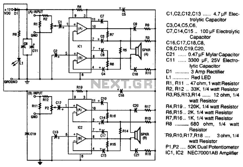
The 20-W + 20-W stereo amplifier consists of two complete, separate 20-W RMS bridge-type amplifiers. The input signal source is brought into the amplifier through a voltage divider network, which is composed of resistors R1, R2, and potentiometer P1....