
First-Response Monitor with SCR (Quiz Alarm)
")
In the context of electronic monitoring systems, a first-response monitor circuit employing cross-coupled Silicon Controlled Rectifiers (SCRs) is designed to detect and respond to specific conditions or events. The circuit typically consists of two SCRs configured such that the triggering of one SCR can influence the operation of the other, thereby creating a feedback loop that enhances the sensitivity and reliability of the monitoring function.
The circuit operates by utilizing the inherent properties of SCRs, which are semiconductor devices capable of controlling current flow. When a triggering signal is applied to the gate of the first SCR, it enters the conductive state, allowing current to flow through it. This action can generate a voltage change that is fed back to the gate of the second SCR, causing it to turn on as well. This cross-coupling mechanism ensures that the circuit remains in a stable state until the monitored condition changes, at which point the SCRs can reset and signal an alarm or take another action.
The design of the first-response monitor circuit can incorporate additional components such as resistors, capacitors, and diodes to refine the response time and sensitivity. The choice of these components will depend on the specific application requirements, including the types of signals being monitored and the desired speed of response.
Overall, the use of cross-coupled SCRs in a first-response monitor circuit provides a robust solution for applications requiring immediate detection and response to critical events, making it suitable for various safety and alarm systems in industrial and commercial environments.A pair of cross-coupled SCRs can be used to build a first-response monitor circuit, as shown in the schematic diagram below. First-response circuit is.. 🔗 External reference
Related Circuits

This simple robot responds to light and avoids obstacles without the need for a microcontroller, programmer, or PC. The primary component in the circuit is a window discriminator, which functions as an advanced window comparator. Resistors R1 and R2,...

Flashing occurs each time the capacitor discharges through the turned-on SCR. When the discharge current falls below the SCR holding current, the SCR turns off, and the capacitor begins charging for another cycle. The circuit will maintain a slower...

This circuit was designed on request to remotely monitor when a couple of electric heaters have been left on. Its sensor must be placed in contact with the feeder to be able to monitor when the power cable is...

When the battery voltage is 11.5V or less, transistor Q1 is activated, and LED D1 will illuminate. When the battery voltage is between 11.5V and 13.5V, transistor Q2 is activated, causing LED D2 to light up. At a battery...
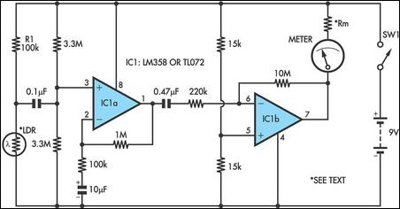
Strictly speaking, this simple circuit should not work. How could anyone expect an ordinary light-dependent resistor (LDR) photocell to detect the change in blood flow as the heart pulsates through a fingertip in natural daylight? The secret lies in...
The ADM1066 from ADI Company is a monitoring device designed to manage various configurable sequencing applications. It features 12 ADCs and 6 8-bit DACs with a voltage output precision exceeding 0.5% at 25 degrees Celsius. This device is primarily...