
In-line wattmeter
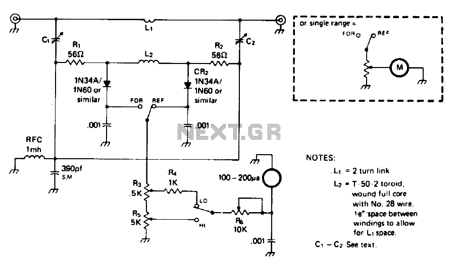
The circuit described functions as a frequency-independent bridge, suitable for applications across the amateur HF spectrum. The design relies on careful selection of component values, particularly the inductor L2, the voltage divider capacitors C1, C2, and C3, as well as the resistors R1 and R2. It is crucial that R1 and CR1 are matched to optimize performance and ensure accurate calibration across the specified frequency range.
In this configuration, R1 should be significantly smaller than the reactance of L2. This condition is essential to prevent any adverse impact on the current flowing through L2, which is influenced by the transmission line current in L1. The interaction of these currents is critical for maintaining the integrity of the circuit's operation.
The lower frequency limit of the bridge is governed by the ratio of R1 and R2 to the inductance Ls. As the frequency decreases, the reactance of L2 will increase, and there will be a point where the combined resistance of R1 and R2 becomes comparable to the reactance of L2. This point marks the cutoff frequency, beyond which the circuit may no longer maintain its intended operational characteristics.
To achieve optimal performance, it is advisable to simulate the circuit using electronic design automation (EDA) tools to verify the component values and their effects on circuit behavior across the desired frequency range. This simulation can help identify any potential issues related to component tolerances and interactions, ensuring that the circuit remains functional and accurate throughout its operational spectrum.The circuit is not frequency sensitive. Its calibration will be accurate over a wide frequency spectrum, such as the entire amateur hf spectrum, if the values of L2, the voltage divider capacitors Cl-2 and C3, and the resistances of Rl-2 are chosen properly. Rl-2 and CR1-2 should be matched for best results Generally, Rl-2 must be small compared to the reactance of L2 so as to avoid any significant effect on the L2 current which is induced by the transmission line current flowing through LI. The lower frequency limit of the bridge is set by the Rl-R2/Ls ratio, and the cutoff is at the point where the value of Rl-R2becomes significant with reference to the reactance of L2 at that frequency point.
🔗 External reference
Related Circuits
The power is measured by the circuit AD8307 over a 50 ohm dummy load. An A/D converter of 12 bit converts the analog output from the AD8307 to a digital number. Since the AD is a 12 bit A/D,...
This sound wattmeter utilizes a series of colored LEDs as a scale to display the relative power output of an amplifier in watts. It is designed for easy integration into a speaker box, requiring only a connection to a...

A simple audio watt meter circuit or an audio power or audio level meter circuit with diagram and schematics to measure amplifier audio output power in watts. The audio watt meter circuit is designed to measure the output power of...
This project will explain how I build my new wattmeter. This watt meter will be able to measure power from 300nW to 30W @ (0-500MHz). This wattmeter is based up on a dummy load of 50 ohm which can...