
DC shunt regulator power supply circuit
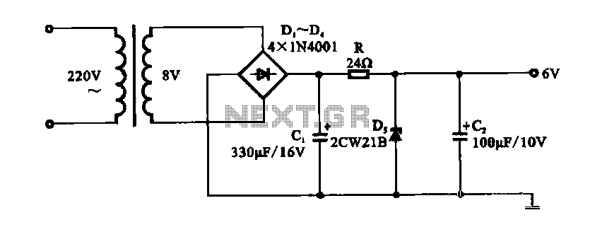
The DC shunt regulator power supply circuit is designed to provide a stable output voltage while being simple in construction. The initial stage involves a step-down transformer that reduces the high voltage AC input to a lower AC voltage level. The 8V AC output is then rectified using a bridge rectifier, which converts the AC voltage into a pulsating DC voltage. The resulting DC voltage is typically around 1V, which is insufficient for most applications, necessitating further regulation.
After rectification, the pulsating DC voltage is smoothed using two electrolytic capacitors. These capacitors serve to filter out the ripples in the DC voltage, thereby providing a more stable voltage to the subsequent regulation stage. The center-tapped transformer configuration allows for the use of zener diodes, which are critical in maintaining the output voltage at a constant 6V. The zener diodes operate in reverse breakdown mode, clamping the voltage to the desired level.
The use of resistors in conjunction with the zener diodes ensures that the voltage remains stable under varying load conditions. However, it is important to note that the current drawn by the zener diodes remains constant, even when the load is minimal. This characteristic leads to inefficiencies, especially in low-load scenarios, where the regulator may draw more current than necessary, potentially leading to overheating or reduced lifespan of the components.
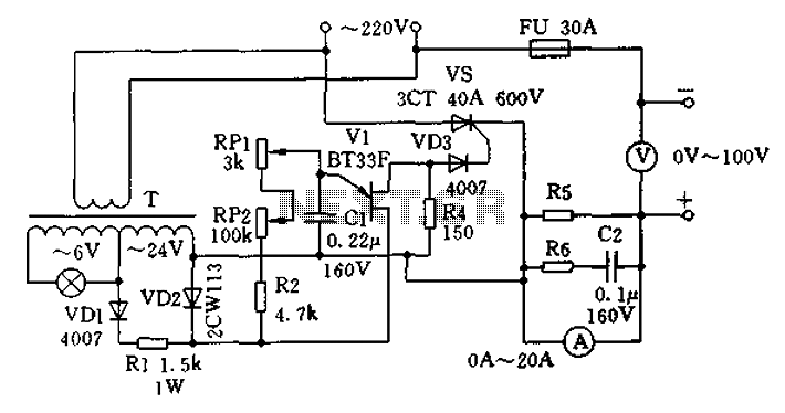
In summary, while the DC shunt regulator power supply circuit is effective for providing a regulated DC output, its design limitations restrict its use to applications with low and stable load currents. Careful consideration of the load requirements and potential inefficiencies associated with the zener diodes is essential for optimal performance.DC shunt regulator power supply circuit Shown is a DC power supply circuit in parallel using the radio circuit, after the AC 22V output voltage by the step-down transformer 8V AC low voltage, 8V AC voltage through a bridge rectifier output of about 1V DC, filtered and then by ct, R, Ds regulator, C2 filtered output of 6V regulated DC. Circuit electrolytic capacitor using two smoothing filter. Use diode voltage regulated power supply circuit is simple, but the biggest drawback is that in case of load power zener diodes are still current consumption, the load current is smaller the current flowing through the regulator is greater, because this two shares equal to the sum of a constant current.
So the regulator power supply only for the load current is small, and the change is not the occasion.
Related Circuits
The Accu charger circuit is straightforward and simple to construct, requiring no more than ten components. In addition to its ease of assembly, this charger circuit is also cost-effective and highly efficient. The circuit requires a power supply from...
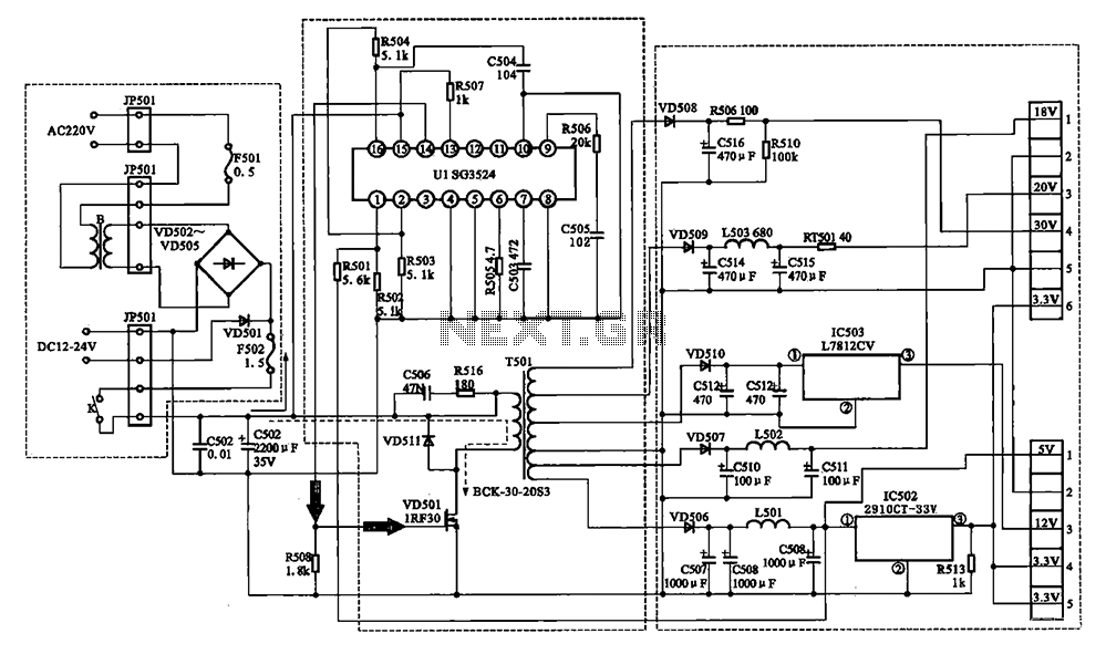
The Changhong DVB-2000 digital satellite receiver features a switching power supply circuit. This circuit primarily comprises a power input section, an oscillation switching circuit, and a DC output section. The power input circuit receives 22V AC from a step-down...
The output frequency can be altered based on the division ratio of the comparison frequency in the 10 kHz unit, with the division ratio set to 1024 in this circuit. Given that the amateur radio bandwidth in Japan is...
The charging apparatus depicted in the schematic circuit has a maximum output current of 20A and a maximum charging voltage of 80V. It can be adjusted starting from 0V, making it suitable for charging various types of batteries. The...
This circuit is a motion detection sensor that utilizes a light source and a detector in the form of an infrared motion detector. The motion sensor employs an infrared LED and a phototransistor. The sensitivity of the sensor can...
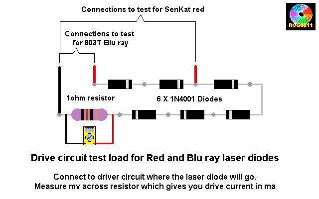
A guide will be posted on how to test a DDL circuit before integrating the LD. The process aims to ensure clarity and accuracy throughout. To properly test a DDL (Direct Drive Laser) circuit before adding the LD (Laser Diode),...