
Inductance and Capacitance Meter Adapter
This project involves the design and assembly of an L-C meter and capacitance meter, aimed at measuring inductors and capacitors with precision. The L-C meter circuit is based on the design by Iulian Rosu, which provides a reliable means of measuring inductance while minimizing errors from resistance and core saturation effects. The added range switch position for 20 mH allows for extended measurement capabilities, although it is acknowledged that this may introduce some accuracy limitations.
The integration of a 10X gain stage following the detector enhances the usability of the voltmeter across both measurement types, ensuring consistent readings. The choice of a 3.2 MHz oscillator instead of a dedicated 100 kHz crystal not only reduces costs but also simplifies the design. The triggered one-shot circuit for capacitance measurement, driven by the clock, ensures that measurements are taken at predictable intervals, which is critical for accuracy.
The project requires careful selection of resistor values to achieve the desired measurement ranges. For instance, the 200 µF range necessitates a lower resistor value of 510 ohms, while the 2 nF range demands a higher value of 510 k ohms. This careful balancing act is crucial to maintain the integrity of the measurements across the entire range.
Furthermore, the need for a discharge circuit is emphasized, as it ensures that capacitors are fully discharged before subsequent measurements. This is particularly important for capacitors that exceed the selected measurement range, as they must start from a zero voltage state to ensure accurate readings.
The physical layout of the circuit board, measuring 4.25" x 4.75", presents challenges in terms of space management, especially when integrating components such as a 12V transformer, rotary switches, and test terminals. The assembly process is intricate, requiring multiple steps to ensure proper alignment and functionality. The complexity of the build process highlights the need for meticulous planning and execution to achieve a compact and efficient design.Another project started with three others not finished. What would my Dad say Well one thing he would say is, "Warn people that this project is under construction and has not been proved to work yet". You have been warned. I had to use a signal generator, resistor, and oscilloscope to measure the value of an inductor for my battery-charger projec
t. That was just irritating. So, after looking for a reasonably priced L-C meter and finding none, I started looking at articles for building one. There are many on the net, but I picked a circuit by Iulian Rosu. It looked the best for checking all sizes of inductors with minimum errors due to resistance and core saturation.
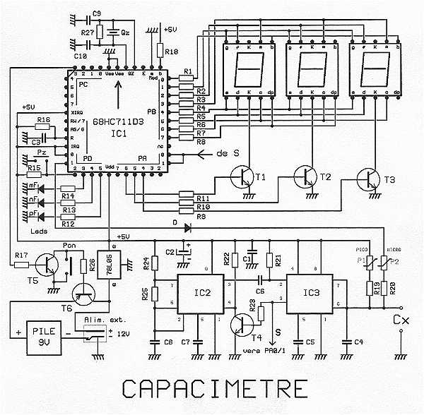
The capacitance meter was thrown in for convienience and does not pretend to be a circuit in the league with a Gary Novak`s femto farad circuit. It is just a simple capacitance checker. If you look at the schematic below you will see that it is just a re-drawn version of the schematic for Iulian Rosu`s adapter shown in the qsl.
net webpage. I added one more position to the range switch to go to 20mH. There is probably a good reason why the increase in range won`t work. I am hoping it is just accuracy. At 20 mH I am just looking for a range confirmation, not an actual measurement. The other change I made to the inductance adapter circuit was to add a 10X gain stage after the detector. I wanted the inductance and capacitance adapters to use the same voltmeter scale and the capacitance adapter did not work so well on the 200mV scale.
Oh yes! I also had to change the clock to a 3. 2MHz oscillator with division down to 100kHZ. It was more cost effective (cheaper) to use the 3. 2MHzcrystal and a 4060 IC than to buy a 100kHz crystal. The capacitance circuit is a triggered one-shot that is driven by the crystal clock. The clock is there, so why not use it Simply pick the resistors to give the correct averaged output voltage for the available clock periods. Because I wanted full-scale ranges from 2nF to 200uF, the resistor value range would have to be from 10 to 1 megohm, a couple of the timing resistors would have to be 1-Watt rated, and a separate dicharge power-transistor and driver would be needed and a 1-amp power supply would be needed.
This would not work well. I had to use two clock periods and two voltages in order to keep the resistor values in a reasonable range of values. The clock periods are a multiple of 100; that allowed me keep the resistor value for the 200uF range down to 510 ohms and still retain a reasonable 510k ohms for the 2nF range.
By using 9V for the timer and timing resistors, I could use the low-time of the timing pulse for the measurement time and the high-time of the pulse for reset. A reset time is needed to get the big capacitors dicharged after measurement, but it is also needed to discharge a over-range capacitor that only gets partially charged during the measurement time.
Without the discharge, a capacitor with value greater than the selected measurement range, would not be starting from 0V during the measurement period. I should have used double-sided board or planned layout to better fit an available box size. What I got was a 4. 25" x 4. 75" board. When you add a 12V transformer ( I don`t like wall warts), two rotary switches, the test terminals, and the voltmeter terminals the adapter box is pretty big and there is a lot of wasted space in standard boxes.
What to do This was not easier. It required too many steps. Five steps to glue it together then cut it in two, two steps to put in the alignment posts and drill holes for the screws, one more step to cut holes for the components, and finally, four steps to mask off areas and paint the box. That is 12 steps, so in a rush it would have taken two weeks. I think it took me two months at my pace. 🔗 External reference
Related Circuits
The proposed capacitance is a very powerful assembly to measure in 7 ranges capacitors of 1 pF to 999 uF, with an excellent precision of about 10^-3. The range change is fully automatic. The display shows 3 digits with...
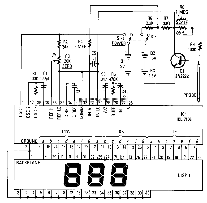
The ICL, specifically the Intersil ICL 7106, integrates an analog-to-digital converter, a 3.5-digit LCD driver, a clock, a voltage reference, seven-segment decoders, and display drivers. An alternative component, the ICL7107, is available for driving seven-segment LEDs. The probe body...
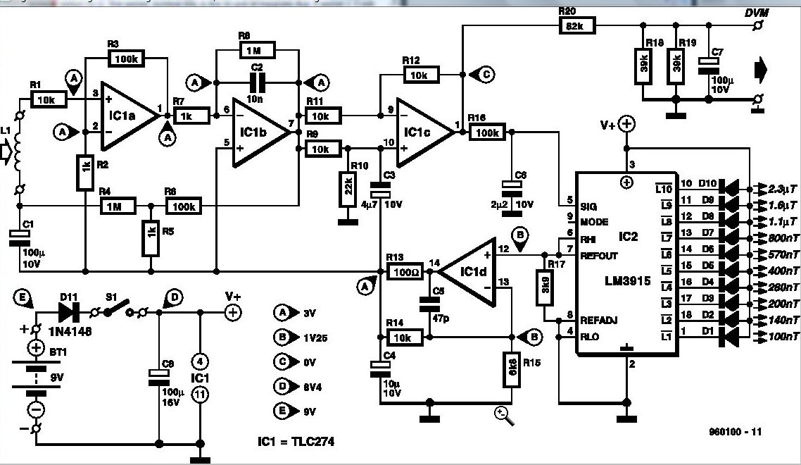
Some experts believe that static magnetic fields (SMFs) may affect the physical well-being of individuals. If one subscribes to this viewpoint, the magnetic-field meter described here will aid in locating sources of SMFs and assessing their strength. These results...
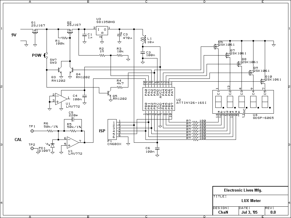
Photo diode outputs light current that is well proportional to input light power when it is used in short mode. In this lux meter, the output current is converted to voltage with an I-V converter, it is captured by...
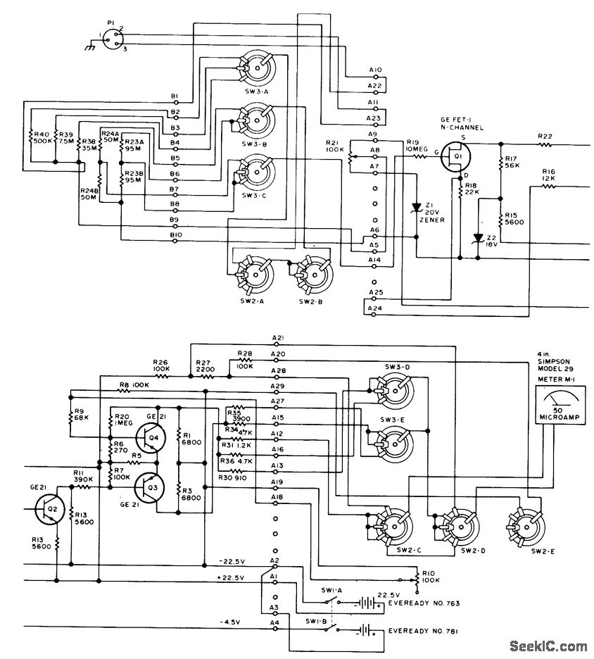
This circuit utilizes a probe that contains a Clairex 905HN light-dependent resistance element, which is connected to a DC differential amplifier. The amplifier drives a meter with a specially calibrated scale. The article outlines the calibration procedure. A switching...
A highly effective method for providing continuous and direct indication of electrostatic voltmeter (ESV) readings, even in large lecture halls, is to integrate this instrument with a tonal voltmeter (TVM). The TVM emits an audible tone of constant amplitude,...
Warning: include(partials/cookie-banner.php): Failed to open stream: Permission denied in /var/www/html/nextgr/view-circuit.php on line 713
Warning: include(): Failed opening 'partials/cookie-banner.php' for inclusion (include_path='.:/usr/share/php') in /var/www/html/nextgr/view-circuit.php on line 713