
Inexpensive Pulse Generator For Logic Troubleshooting
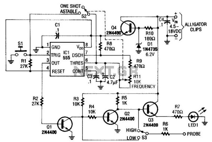
The pulse generator circuit utilizes a 555 timer IC in an astable or monostable configuration, depending on the selected mode via switch S2. In astable mode, the circuit continuously generates square wave pulses, while in monostable mode, it generates a single pulse in response to a trigger signal. The frequency of oscillation in astable mode is determined by the values of R1 and C2, where R1 is the timing resistor and C2 is the timing capacitor. The frequency can be calculated using the formula:
\[ f = \frac{1.44}{(R1 + 2R2) \times C2} \]
In this configuration, R1 can be adjusted to fine-tune the frequency within the specified range of 5 to 200 Hz, while decreasing C2 can further increase the frequency.
Transistors Q1 and Q2 are configured in such a way to ensure that the output pulse has a fast rise time, which is critical for applications requiring precise timing and signal integrity. This fast rise time is beneficial in logic troubleshooting, where clarity of pulse edges can significantly affect the diagnosis of circuit behavior.
Transistor Q4 acts as a voltage regulator, ensuring that the circuit operates within the specified voltage range of 4.5 to 18 VDC. This feature allows for flexibility in power supply options, accommodating various testing environments and equipment.
The inclusion of LED1 as an operational indicator provides visual feedback on the circuit's functionality. When the circuit is powered and operational, LED1 illuminates, indicating that the pulse generator is functioning as intended. This is particularly useful in troubleshooting scenarios, allowing the user to quickly ascertain circuit status without needing additional testing equipment.
Overall, this pulse generator circuit is a versatile tool for logic troubleshooting, offering adjustable frequency output, reliable operation, and user-friendly indicators. Built around a 555 timer IC, this pulse generator can be built into a probe for logic troubleshooting. Rll is frequency controlled and gives a range of about 5 to 200 Hz. C2 can be reduced for higher frequencies. S2 selects one shot or pulse operators. Ql and Q2 provide a fast rise-time pulse, which acts as a clipper amplifier. Q4 acts as a regulator. The supply can be anything from about 4.5 to 18 Vdc. LED1 is an indicator that shows circuit operation. 🔗 External reference
Related Circuits

This circuit is capable of generating up to 1 W of audio power to drive a speaker or horn. When the CDS cell is exposed to light, its resistance decreases, activating NOR gate (a). This activation causes gates (a)...
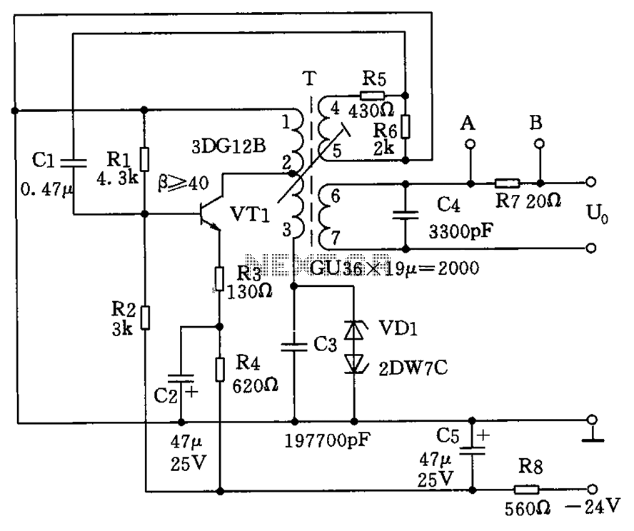
The circuit depicted in the figure allows for the selection of optimal operating conditions and a suitable allocation of the temperature coefficient for the resonant circuit components. The resonance occurs at both ends of the circuit. Additionally, the exchange...
This circuit generates an accurate and adjustable sine-wave output by removing harmonics from a square wave. This circuit utilizes a harmonic filter to transform a square wave input into a sine wave output. The primary function of this circuit is...
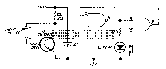
There are two switches: a memory disable switch and a pulse polarity switch. The memory disable switch is a push-button that resets the memory to a low state when pressed. The pulse polarity switch is a toggle switch that...
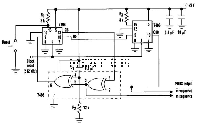
In this circuit, an additional exclusive-OR gate is connected after the modulo-2 feedback, with CI and R2 applying the supply turn-on ramp into the feedback loop. This provides sufficient transient signal so that the PRBS generator can self-start during...
The VTG-01 is designed to display user defined text over a composite video signal. This is useful in a multitude of different applications such as adding titles to home movies and adding custom text to security videos. Text can...