
Pseudo-Random Bit Sequence Generator Circuit

The circuit design incorporates an exclusive-OR gate positioned after a modulo-2 feedback mechanism, which plays a crucial role in the operation of a Pseudo-Random Binary Sequence (PRBS) generator. The configuration utilizes components CI and R2 to introduce a supply turn-on ramp into the feedback loop, effectively generating a transient signal. This transient signal is essential for enabling the PRBS generator to initiate its operation autonomously upon power-up, ensuring reliable performance.
The shift register in this design has a length of 10, with feedback connections established at stages 3 and 10. This arrangement allows for the generation of both true and inverted maximal length sequence outputs, which are fundamental for various digital communication applications. The direct application of input to the feedback loop is a significant aspect of this design, as it enhances the reliability of the circuit. Unlike traditional methods that utilize an RC configuration for resetting the shift register, which can lead to unpredictable initial states, the current approach ensures a more deterministic behavior during startup.
This circuit is particularly advantageous in scenarios where consistent and repeatable operation of the PRBS generator is required. The careful selection of feedback stages and the implementation of the exclusive-OR gate contribute to the overall stability and performance of the system, making it suitable for high-speed digital applications. The design emphasizes the importance of transient signals in circuit initialization and the benefits of direct feedback mechanisms in enhancing operational reliability. In this circuit, an additional exclusive-OR gate is connected after the modulo-2 feedback, with CI and R2 applying the supply turn-on ramp into the feedback loop. This provides sufficient transient signal so that the PRBS generator can self-start a power-up. A shift-register length of 10 is shown with feedback at stages 3 and 10, providing true and inverted maximal length sequence outputs.
This technique applies an input directly to the feedback loop. Therefore, it`s considered more reliable than applying an RC configuration to the shift-register reset input to create a random turn-on state. 🔗 External reference
Related Circuits
This infrared light valve has more parts, so it works better and more reliable for alarms. The circuit responds less ambient light. The light valve consists of a transmitter and a receiver. The transmitter consists of a NE 555...
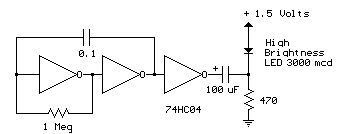
Several 1.5 V LED flasher circuits can be found online, and four of them are presented here. The flasher circuits operate on a single 1.5 V power supply. The design of a 1.5 V LED flasher circuit typically involves a...
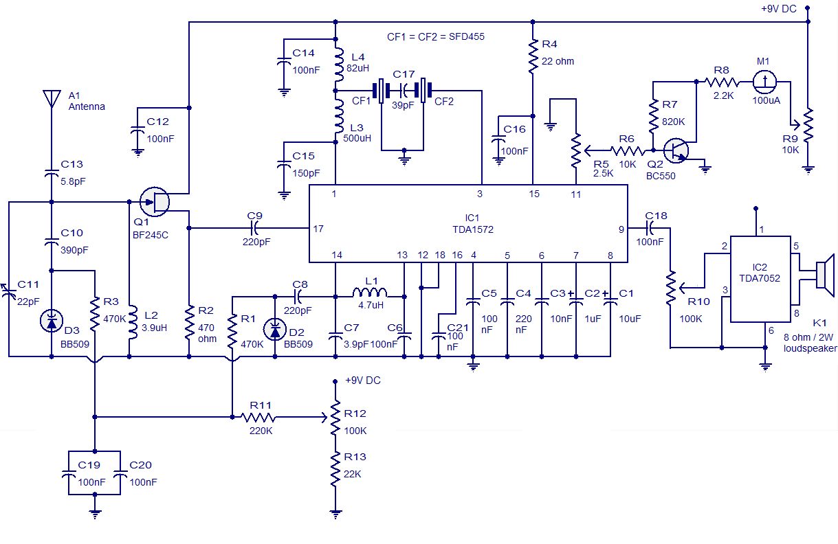
High-quality AM radio circuit based on the TDA1572 IC. The AM radio receiver circuit operates from 9V DC and has a 1W output power. It requires a minimum number of external components. The AM radio circuit utilizing the TDA1572 integrated...
It is easy to miss the sound of a doorbell while watching TV. This circuit addresses the issue by providing a visual indication, such as a lamp or an LED. Connecting a lamp directly in parallel with the doorbell...
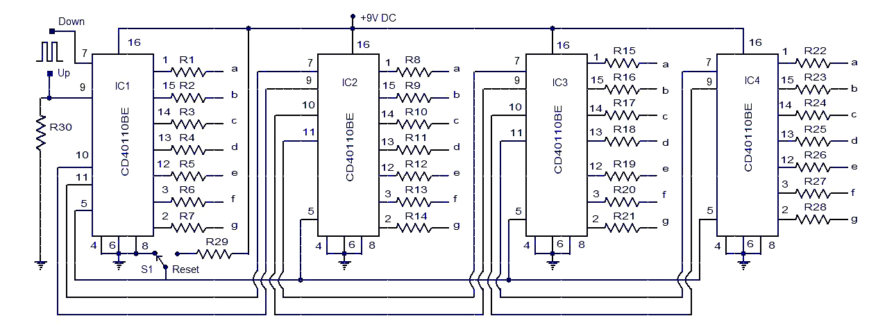
This circuit diagram illustrates a simple up/down counter suitable for various applications. It utilizes the CD40110BE IC, a CMOS decade up/down counter. Common cathode seven-segment displays are connected to the outputs of each IC. The display connected to IC1...

An audio power amplifier circuit for a 3-watt stereo amplifier using the MAX 7910 IC is explained below. The audio power amplifier circuit utilizing the MAX 7910 IC is designed to deliver a maximum output power of 3 watts per...
Warning: include(partials/cookie-banner.php): Failed to open stream: Permission denied in /var/www/html/nextgr/view-circuit.php on line 713
Warning: include(): Failed opening 'partials/cookie-banner.php' for inclusion (include_path='.:/usr/share/php') in /var/www/html/nextgr/view-circuit.php on line 713