
infra red ir led flood light circuit
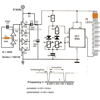
The 4049 voltage doubler circuit operates by utilizing the principles of capacitive charge and discharge, where two capacitors and diodes are arranged to effectively double the input voltage. The circuit typically consists of two diodes and two capacitors. During the first half of the AC cycle, one capacitor charges through the first diode, while the second capacitor charges through the second diode during the opposite half cycle. This configuration allows the output voltage to reach approximately double the input voltage, thus converting the 9 V from the PP3 battery to around 15 V.
This boosted voltage is crucial for the operation of the 555 pulse modulator, which is commonly used in various applications such as timers, pulse generation, and oscillators. The 555 timer can be configured in monostable or astable modes, allowing for versatile control over the LED operation. In this circuit, the 555 timer is likely configured to produce a square wave signal that drives the IR LEDs. The modulation of the LED output can be adjusted by changing the resistor and capacitor values connected to the 555 timer, enabling variations in pulse width and frequency.
The use of a single PP3 9-volt battery is advantageous for this circuit, as it provides a compact and portable power source. Despite its small size, the circuit is designed to maximize the efficiency of the IR LEDs, which are known for their high light output relative to power consumption. The combination of the voltage doubler and the 555 pulse modulator allows the circuit to achieve impressive infrared illumination levels, making it suitable for applications such as remote controls, night vision devices, and security lighting systems.
Overall, this circuit exemplifies an efficient design that leverages basic electronic components to achieve high performance while maintaining simplicity and portability.The 4049 section is the basic voltage doubler circuit which effectively boosts the 9 V supply to a level of around 15 V which further becomes the supply voltage for the next 555 pulse modulator section. The main feature of this infrared IR LED flood light circuit is that it utilizes just a single PP3 9 volt battery and yet is able to provide l
ights (IR) at dazzling levels. 🔗 External reference
Related Circuits
The AD2S80A RDC tracking monolithic integrated circuit is Analog Devices' latest generation RDC. It can be utilized for synchro, resolver, and inductive synchronizer digital conversion. This device integrates advanced CMOS logic and bipolar high-accuracy linear circuits using a BiMOS...
The circuit involves infrared phototransistor pairs positioned at three locations within a maze, including the endpoint. The maze is designed to be narrow enough for a single finger to slide through, and as fingers pass the phototransistors, a sound...
A fixed three-terminal integrated voltage regulator can be directly employed in various electronic devices as a voltage regulator. It features internal protections such as overcurrent protection, thermal protection, and safe operating area protection, making the circuit easy to use,...
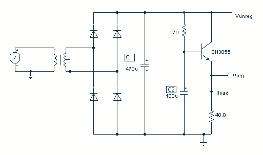
To avoid excess ripple output on a power supply feeding a heavy load, usually a large value capacitor is chosen following the rectifier. In this circuit, C1 is only a 470uF capacitor. The gyrator principle uses the effect that...
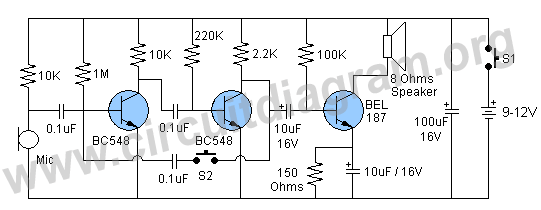
A high-quality and straightforward intercom circuit utilizing only three transistors. By pressing switch S2, the circuit generates ringing signals. To create a two-way intercom, two identical circuits can be constructed and combined as illustrated in diagram 2. The circuit's...
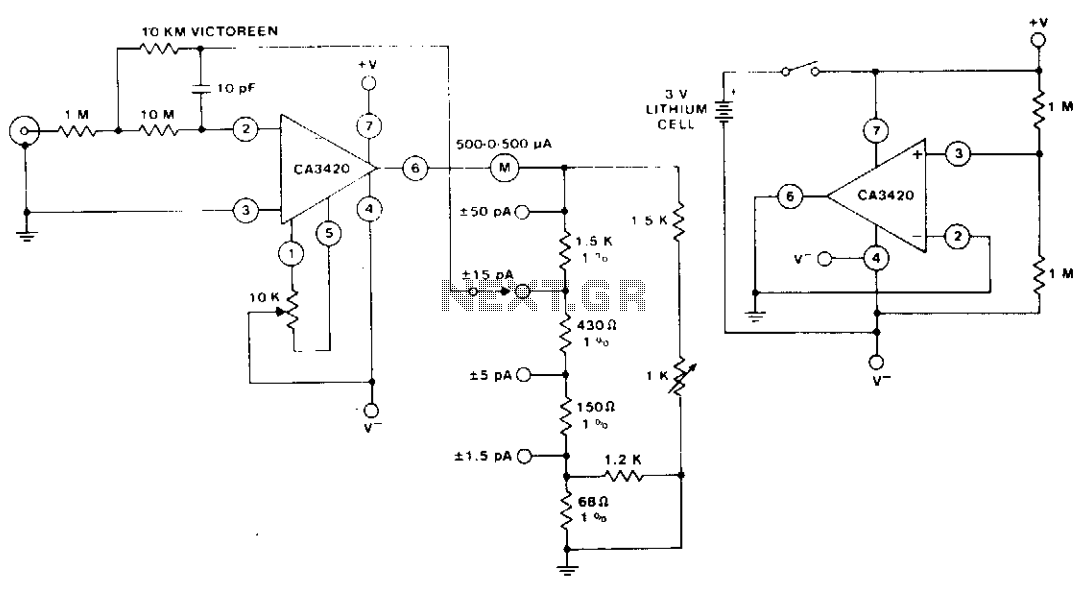
The circuit utilizes the extremely low input current (0.1 pA) of the CA3420 BiMOS operational amplifier. With only one 10 megohm resistor, it achieves a range from ±50 pA maximum to a full-scale sensitivity of ±1.5 pA. Additionally, by...
Warning: include(partials/cookie-banner.php): Failed to open stream: Permission denied in /var/www/html/nextgr/view-circuit.php on line 713
Warning: include(): Failed opening 'partials/cookie-banner.php' for inclusion (include_path='.:/usr/share/php') in /var/www/html/nextgr/view-circuit.php on line 713