
Infra Red Remote Control
This circuit design effectively demonstrates the principles of infrared detection and amplification. The SFH2030 photodiode serves as the primary sensor, converting infrared light into an electrical current. The CA3140 operational amplifier, configured in differential mode, enhances the sensitivity of the circuit by providing necessary amplification of the small currents generated by the photodiode.
The output voltage from the op-amp is directly proportional to the current detected by the photodiode, making it easy to quantify the strength of incoming infrared signals. The inclusion of an LED provides a visual indication of infrared detection, allowing for straightforward operation without the need for additional diagnostic equipment.
For practical implementation, the circuit can be powered by either a 12-volt power supply or a 9-volt battery, providing flexibility for various applications. The choice of operational amplifier is critical; standard op-amps like the 741 or LF351 are unsuitable due to their inadequate response characteristics for this specific application.
In summary, this circuit is a valuable tool for measuring infrared signal strength, useful in applications such as remote control testing and infrared communication analysis. The design's simplicity, combined with effective performance, makes it a suitable project for both educational purposes and practical applications in electronics.This circuit is the result of Andy Collinson research. He has used a photodiode, SFH2030 as an infra red sensor. A MOSFET opamp, CA3140 is used in the differential mode to amplify the pulses of current from the photodiode. LED1 is an ordinary coloured led which will light when IR radiation is being received. The output of the opamp, pin 6 may be c onnected to a multimeter set to read DC volts. Infra red remote control strengths can be compared by the meter reading, the higher the reading, the stronger the infra red light. He aimed different remote control at the sensor from about 1 meter away when comparing results. For every microamp of current through the photodiode, about 1 volt is produced at the output. A 741 or LF351 will not work in this circuit. Although he has used a 12 volt power supply, a 9 volt battery will also work here. 🔗 External reference
Related Circuits
Wine doesn't like subzero temperatures, and during wintertime, my wine cellar got pretty cold. There was an electric heating element, but the thermostat was broken, so it was either full burn or nothing. That's how the temperature monitor/controller came...

A simple frequency meter or frequency counter circuit featuring an LCD display and an AVR microcontroller. This includes a DIY schematic circuit diagram and embedded C code. The frequency meter circuit is designed to measure the frequency of input signals...
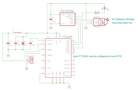
The IR Widget operates in a manner that ensures compatibility with modern multitasking operating systems. It can determine the carrier frequency and demodulate the carrier in both the digital and analog domains. The captured information can be utilized to...
Amplifier with tone controls and soft switching. Notes: The soft switching is enabled by a BD131 transistor configured as a switch in an emitter follower arrangement. The collector is connected to a permanent load. The described amplifier circuit incorporates tone...
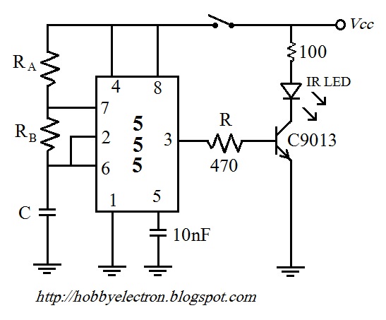
The remote control circuit comprises two main components: a transmitter and a receiver. The transmitter circuit is controlled by an NE555 integrated circuit (IC), while the receiver operates based on the frequency of the signal emitted by the transmitter....

A passive high-pass filter has been added after the output of the operational amplifier (op-amp) to eliminate DC offset, with the op-amp powered by +12V and the negative supply at 0V. A feedback resistor (Rf) of 500K Ohms is...