
remote control circuit
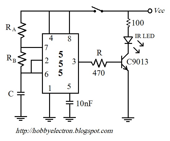
The remote control circuit is a fundamental example of wireless communication, utilizing a transmitter and receiver setup to convey signals. The NE555 timer IC serves as a versatile component in the transmitter circuit, generating a pulse-width modulated (PWM) signal at a specific frequency. This frequency is determined by the values of external resistors and capacitors connected to the NE555, allowing for customization based on the application requirements.
In the receiver section, the LM567 is a phase-locked loop (PLL) that detects the frequency of incoming signals. The design of the receiver includes a variable resistor (R1), which enables fine-tuning of the circuit to enhance the sensitivity and accuracy of the signal detection. When the transmitter is activated, it continuously emits a signal at the predetermined frequency. The receiver, upon receiving this signal, will output a corresponding voltage that can be further processed or used to control other devices.
The schematic diagram illustrates the interconnection between the NE555 and LM567, along with the necessary passive components such as resistors and capacitors. Each channel in the receiver is designed to respond to different frequencies, ensuring that multiple remote control units can operate without interference. The recommended frequency separation of 5 kHz between channels aids in minimizing crosstalk and enhancing the reliability of communication.
Overall, this remote control circuit exemplifies the principles of frequency modulation and detection, showcasing the practical application of integrated circuits in electronic design. Proper calibration and adjustment of the components are crucial for achieving optimal performance and ensuring that the system operates effectively within its intended range.Remote control circuit consists of two parts, one is the transmitter and the other is the receiver. A simple schematic diagram of the remote control. IC transmitter transmitter circuit is controlled by NE555. Receiver circuit works by the frequency of the signal, which is emitted by the transmitter circuit. Transmission frequency of the signal mus t be equal to the decoder frequency receiver circuit. The frequency generated NE 555 is the same as the receive frequency of the IC LM 567. Resistor R1 is a variable receiver to facilitate the adjustment process. The system works well when the circuit is ready. The first step is the optimization through the transmitter is turned on continuously, while the receiver R1 to set the value of being able to detect the signal from the transmitter. The second part is the receiver is controlled by LM 567. The following is a schematic drawing receptor. In the image at the top of each channel is designed with a different frequency. Given the bandwidth of the frequency detection signal LM 567, between the frequencies on which they owe a big enough difference, let`s try with a difference of 5 KHz.
🔗 External reference
Related Circuits
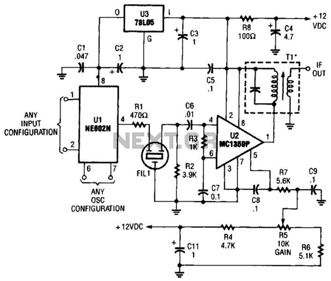
By using an NE602 with a filter and an MC1350P IC, a front end and an IF system for a basic superheterodyne receiver can be built with few parts. Tl is any suitable IF transformer for 262 kHz, 455...
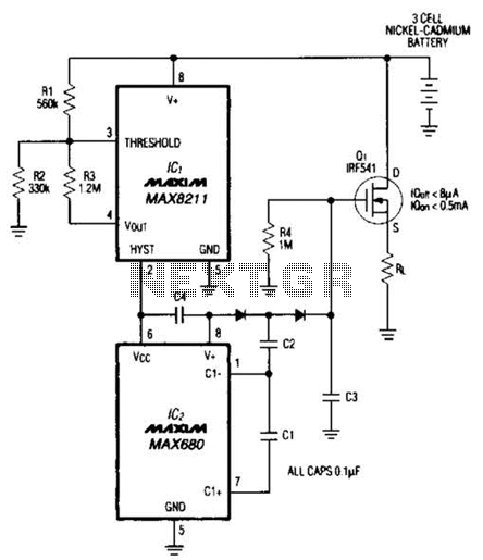
Deep discharge can damage a rechargeable battery. By disconnecting the battery from its load, this circuit halts battery discharge at a predetermined level of declining terminal voltage. Transistor Q1 acts as the switch. The overall circuit draws about 500µA...
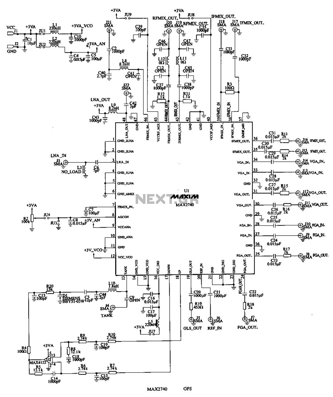
The MAX2740 is a complete GPS receiver down converter chip that processes the signal from the antenna to the input of digital signal processing. The receiver channel of the MAX2740 includes a low-noise amplifier (LNA), a downconverter, a variable...
This circuit produces a two-tone effect similar to the cuckoo song. It is suitable for use in doorbells or other applications due to its integrated audio amplifier and loudspeaker. When utilized as a sound effect generator, it can be...
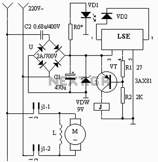
The circuit operates based on the interaction between an infrared light-emitting diode (VD1) and an infrared receiver diode (VD2). When VD1 emits infrared radiation, it is detected by VD2, which causes a decrease in its internal resistance. This change...
This circuit enables the control of any equipment operating at 115 volts AC. It utilizes the Radio Shack infrared receiver module (MOD), part number 276-137, which can also be sourced from other suppliers listed on the Links page. The...
Warning: include(partials/cookie-banner.php): Failed to open stream: Permission denied in /var/www/html/nextgr/view-circuit.php on line 713
Warning: include(): Failed opening 'partials/cookie-banner.php' for inclusion (include_path='.:/usr/share/php') in /var/www/html/nextgr/view-circuit.php on line 713