
Infrared approach detector / sensor

The internal oscillator generates a frequency signal of approximately 4.5 kHz, determined by the time constant set by resistor R1 and capacitor C1. The rectangular output signal at pin 5 is directed to the base of transistor T1, resulting in the same frequency as the LED's opto-sensor. When the LED's light is reflected off an obstacle and detected by the phototransistor, the input pin 3 of IC1 receives a signal, which is then compared with the frequency of the integrated oscillator. If the two frequencies match, the output of pin 8 is driven to logical '0', and LED L1 lights up. Conversely, if they do not match, the output remains at '1'. The use of a phase-locked loop (PLL) ensures that the circuit is unaffected by ambient light or any extraneous flashes from other light sources. The sensitivity of the detector can be adjusted using potentiometer P1, accommodating a current range between 10-30 mA. Instead of the opto-sensor, various types of components can be used, including a pair of LED and phototransistor. In this latter case, it is crucial that the phototransistor only receives light from the LED through reflection and not directly. A solid-state relay (SSR) can be installed between the output of IC1 and ground, allowing for the management of higher load requirements. It is important to note that the output current from pin 8 can reach up to 100 mA. If the design necessitates maximum output current, LED D1 should be removed.
The circuit employs a phase-locked loop configuration that provides robust performance in detecting obstacles by ensuring that the output remains stable in varying lighting conditions. The detection mechanism relies on the precise frequency matching between the internal oscillator and the reflected light signal captured by the phototransistor. This design allows for flexibility in component selection, enabling the use of alternative opto-electronic devices while maintaining the integrity of the detection process.
The implementation of the solid-state relay (SSR) enhances the circuit's capability to control higher power loads, making it suitable for applications where the output needs to drive significant current. The inclusion of the adjustable potentiometer (P1) allows for fine-tuning of the sensitivity, which is critical in environments with varying levels of ambient light and obstacle reflectivity.
Overall, this circuit design showcases a practical approach to obstacle detection, combining efficiency with adaptability, making it applicable in various industrial and medical settings.Basic operation of the monitor attached to the circuit is to detect objects (obstacles), at distances ranging from a few millimeters to and a few centimeters. Depending circuits used in industry and hospitals. The position sensor IC2 optoapomonotis used a type of Siemens SFH900 someone similar. The sign shows, led to a phase locked circuit (contained in IC1), which compares with signal frequency an oscillator which is also located within the same chip.
For as long as the frequencies of two signals coincide, the pin output of IC1 (pin 8) is still reasonable 'O'. The internal oscillator frequency signal produces approximately 4.5 kHz, based on the time constant set netting R1-C1. The rectangular output signal at pin 5, ends at the base of the transistor T 1, whereby the anathosthinei same frequency as the LED's optoapomonoti.
Provided that the LED flashes reflected in a barrier and are captured by the phototransistor, the input pin 3 of IC 1 receives a signal, the frequency of which compares with that of the integrated oscillator. If two frequencies are identical, the output of IC 8 is driven to logical 'O' and the LED L1 fototholei.
Otherwise the case, the output remains at '1 '. The use of phase locked loop (RLL) guarantees that the circuit is insensitive to diffuse light or any kind of spurious flashes from other light sources. The detector's sensitivity is adjusted via the P1 and the requirements of a stream (if used Materials marked) ranging between 10-30 mA.
In place of optoapomonoti you can place different types of components corresponding or even a pair of LED and phototransistor. In the latter case you should note that the phototransistor to receive the light of LED only through reflection and not directly.
Between the output of IC 1 and ground, you can put a solid-state switch (SSR, Solid State Relay), which is able to supply loads with higher requirements. Remember that the current that can absorb the spike 8 reaches 100 mA. If your design needs require the maximum output current, remove the LED D1. 🔗 External reference
Related Circuits

The temperature sensor provides an input to pin 3 of the NE5037 with a sensitivity of 32 mV/°C. This 32 mV represents the value of one least significant bit (LSB) for the NE5037. The LM334 is a three-terminal temperature...

The primary component in the circuit is the SRI, a TGS812 toxic gas sensor produced by Figaro Engineering Inc. This gas-sensitive semiconductor functions as a variable resistor when exposed to toxic gases, resulting in a decrease in electrical resistance...

This line-following robot sensor, also known as a surface scanner for robots, is a compact, stamp-sized infrared proximity detector designed for short-range detection, typically within 5 to 10 mm. The line-following robot sensor operates using infrared light to detect the...
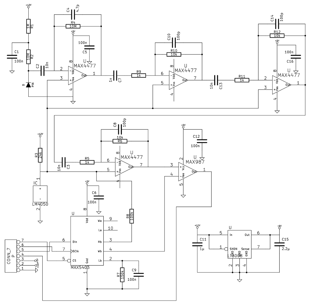
A noteworthy application note from Maxim detailed a gamma-photon detector utilizing a standard PIN diode as its sensing element. The circuit design appeared straightforward, prompting the decision to construct it, as having multiple measurement instruments is always beneficial. The gamma-photon...

The XC61H series is a highly accurate, low power consumption CMOS voltage detector featuring a delay circuit. The detection voltage maintains high accuracy with minimal temperature drift. Output configurations are available in both CMOS and N-channel open drain. As...

Remote temperature measurements must be connected to the relevant test instrument using a cable. Typically, a three-core cable is employed: one core for the signal and two for the power supply. If a two-core cable is necessary, one of...