
Two-Wire Temperature Sensor

The circuit design for remote temperature measurement using the LM45 sensor provides an efficient solution for applications requiring a temperature reading in degrees Celsius. The use of a two-core cable simplifies connections, especially in scenarios where space or weight constraints are critical. The sine-wave generator, comprising A1 and A2, serves as the power source, ensuring a stable alternating voltage supply to the LM45 sensor.
The coupling capacitor C6 is crucial as it allows the alternating signal to pass while blocking any direct current components, ensuring that only the desired alternating voltage reaches the sensor. The voltage-doubling rectifier (D1-D2-C1-C2) is a vital circuit section that transforms the alternating voltage into a usable direct voltage, enabling the sensor to provide an accurate output proportional to the temperature.
Resistor R2 plays an essential role in maintaining the integrity of the output signal by isolating it from capacitive loads that could distort the temperature reading. Choke L1 is designed to effectively couple the sensor output to the signal line while filtering out any unwanted alternating voltage, thus preserving the accuracy of the temperature measurement.
At the receiving end, the low-pass filter network (R3-L2-C4) is designed to eliminate any remaining alternating voltage components that might interfere with the sensor's output. Capacitor C5 ensures that direct current does not flow through R3, which would adversely affect the temperature-dependent voltage signal.
In summary, this circuit design is well-suited for applications where remote temperature measurement is required, providing an effective means of delivering accurate temperature readings over extended distances while maintaining signal integrity and minimizing the impact of alternating voltage interference. The high output load resistance requirement further ensures that the circuit operates efficiently without drawing excessive current.Remote temperature measurements have to be linked by some sort of cable to the relevant test instrument. Normally, this is a three-core cable: one core for the signal and the other two for the supply lines.
If the link is required to be a two-core cable, one of the supply lines and the signal line have to be combined. This is possible with, for in stance, temperature sensors LM334 and LM335. However, these devices provide an output that is directly proportional to absolute temperature and this is not always a practical proposition. If an output signal that is directly proportional to the Celsius temperature scale is desired, the present circuit, which uses a Type LM45 sensor, offers a good solution.
The LM45 sensor is powered by an alternating voltage, while its output is a direct voltage. The supply to the sensor is provided by a sine-wave generator, based on A1 and A2 (see diagram). The alternating voltage is applied to the signal line in the two-core cable via coupling capacitor C6. The sensor contains a voltage-doubling rectifier formed by D1-D2-C1-C2. This network converts the applied alternating voltage into a direct voltage. Resistor R2 isolates the output from the load capacitance, while choke L1 couples the output signal of the sensor to the signal line in the cable.
Choke L1 and capacitor C2 protect the output against the alternating voltage present on the line. At the other end of the link, network R3-L2-C4 forms a low-pass section that prevents the alternating supply voltage from combining with the sensor output. Capacitor C5 prevents a direct current through R3, since this would attenuate the temperature-dependent voltage.
The output load should have a high resistance, some 100 k or even higher. The circuit draws a current of a few mA. 🔗 External reference
Related Circuits
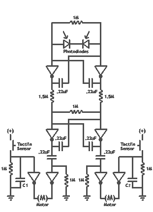
It's basically a photovore with a couple tactile sensors. It's rather complex but can give neat behaviors with modifications to the circuit. At this point I don't have any plans to give more information on this circuit so your...
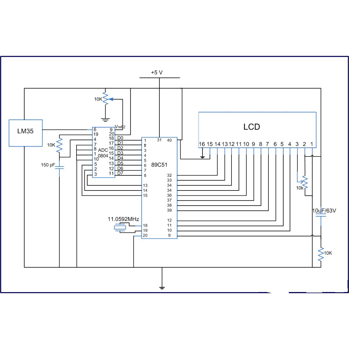
The LM35 series are precision integrated-circuit temperature sensors, whose output voltage is linearly proportional to the Celsius (Centigrade) temperature. The LM35 has an advantage over linear temperature sensors calibrated in Kelvin, as the user is not required to subtract...
A touch sensor relaxation oscillator is utilized in the hysteresis lab. In this schematic, the variable capacitor is represented by a person's finger and a touch plate made from aluminum foil and packing tape. Code was developed for the...
This week's plan is to build a device that warns of the potential for a knockdown, which is the process by which an over-canvassed ship is laid over on her beam-ends. The risk of sinking is high during this...

This circuit illustrates a color sensor circuit diagram. The design is grounded in the principles of optics and digital electronics. The color sensor circuit typically employs a light-sensitive component, such as a photodiode or phototransistor, to detect and differentiate colors...

This is a simple sound sensor schematic that utilizes a single integrated circuit (IC) and two transistors to drive a relay. The schematic allows for sensitivity adjustment using a variable resistor (VR). This design is quite useful and can...