
Infrared automatic hand washing device 3

The infrared automatic hand washing device operates by utilizing an infrared sensor to detect the presence of hands. The power supply section ensures that the entire circuit receives the necessary voltage and current. The fuse (FU) serves as a protective element, preventing overcurrent conditions that could damage the circuit components. The power transformer (T) steps down the mains voltage to a lower level suitable for the circuit operation.
The bridge rectifier (UR) converts the alternating current (AC) output from the transformer into direct current (DC), which is then filtered by capacitors (C1, C2) to smooth out voltage fluctuations. The output is regulated by a three-terminal voltage regulator, which provides a stable DC voltage for the infrared transmitting and receiving circuits.
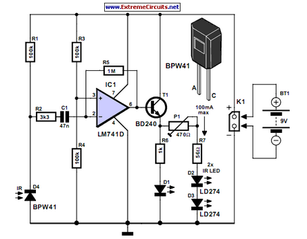
The infrared transmitting circuit emits infrared light, which is reflected off of hands when they are placed within the sensing range. The infrared receiving circuit detects this reflected light, sending a signal to the control circuit. The control circuit processes this signal and activates the washing mechanism, such as a motor or solenoid, to dispense water or soap as needed.
This automatic hand washing device enhances hygiene by minimizing the need for physical contact, thereby reducing the risk of cross-contamination. The simplicity of the circuit design ensures reliability and ease of maintenance, making it suitable for various applications in public restrooms, kitchens, and healthcare facilities.The circuit work theory This infrared automatic hand washing device circuit is composed of power supply, infrared transmitting circuit, infrared receiving circuit and control circuit, the circuit is shown in the figure 9-121. The power supply circuit is made of fuse FU, power transformer T, bridge rectifier UR, filter capacitors C1, C2 and three terminal r..
🔗 External reference
Related Circuits
Many consumer electronic devices such as television sets, VCRs, CD players, and DVD players utilize infrared remote control technology. In certain situations, it is beneficial to extend the range of these remote controls. Infrared (IR) remote controls operate by emitting...
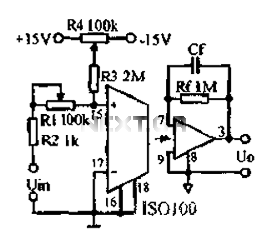
An adjustable gain test is conducted in preparation for an isolation amplifier circuit, utilizing the optical coupling isolation amplifier ISO100. This adjustable gain can form part of a test device for the isolation amplifier. The circuit gain can be...
A simple single-player PONG game utilizing an LED matrix was developed, focusing on the synchronization of signals as observed in an analog PONG game previously constructed. Initially, a 10x10 matrix was envisioned for the ball, leading to the selection...
Having to use the infrared remote control, we will procure in addition to modulate the Nutchip infrared receiver. Do not let the name fool you, because more than one module component that looks like a large transistor. We use...
An efficient automatic solar garden lights circuit with minimal components. The notable feature is that it operates entirely automatically, with the solar panel functioning as a light detector. The automatic solar garden lights circuit is designed to provide illumination in...
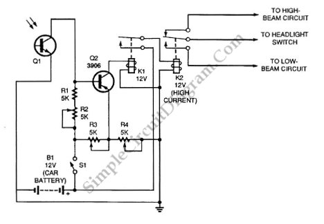
Automatic headlight dimmer circuit diagram for your car's headlight. It ensures safety by providing maximum brightness for the farthest visibility while automatically switching. The automatic headlight dimmer circuit is designed to enhance driving safety by adjusting the brightness of vehicle...