
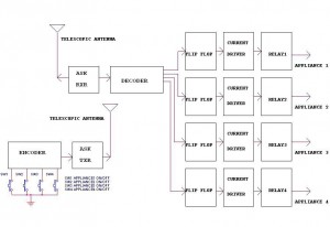
Infrared relay remote control
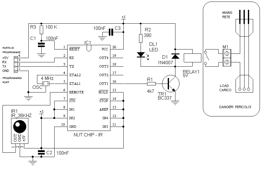
It is very important that the relay be able to withstand with an adequate margin the current required by the lamp. Calculate the required current to the lamp you want to use (A = W / V) and quadruplicate it. For example, a 100W lamp, use a relay rated for 100W/220V = 1.8 * 4-A as a minimum; in practice, fit a model rated for 5A. Also, ensure that the current and voltage ratings of the contacts are suitable for AC applications, as some manufacturers indicate only the voltage.
Since this circuit switches a load connected to the mains, where voltages and currents involved are potentially lethal, great care must be taken regarding safety. It is required to mount the circuit inside a completely insulated plastic enclosure. The programming of the chip and any type of measurement must be done with the circuit and the load strictly unplugged.
Using a pre-made printed circuit board is advisable unless one is very experienced; in that case, a "spacer" board can be utilized. When using a spacer board, it is essential to create a safety zone around the relay terminals and file away the copper "vignettes" to leave an insulating barrier at least 6 mm wide around each contact.
The circuit is designed to switch on and off using the exit code 1 when a specific key is pressed, which is a straightforward task for the Nutchip. To achieve an on-off operation with a single button press, a one-second delay is introduced during which the remote control is not responsive. Each time a button is pressed on the remote, the code is transmitted multiple times within a fraction of a second. The one-second delay allows the remote control to enter "off" mode. Observing the LED behavior will provide insight into this functionality, as it will blink on and off at one-second intervals when the button is pressed continuously.
The assembly process is not particularly difficult; however, caution is necessary to avoid reversing the polarity of the components. A tester should be used to identify the relay contacts before mounting. If a 5-volt relay capable of handling the current demand cannot be sourced, a 12-volt relay can be used instead. In this case, the resistance R2 should be increased to 1000 ohms from +5 volts, and R2 and D1 (cathode side) should be disconnected and then connected to 12 volts.Having to use the infrared remote control, we will procure in addition to modulate the Nutchip infrerossi receiver. Do not let the name fool you, because more than one module component that looks like a large transistor.
We use as a reset Nutchip external RC network consisting of R3 and C1. The capacitors C2 and C3 instead serve as a bypass, and filter feeds Nutchip and infrared receiver. Perch? be effective must be mounted very close to the integrated they have to protect. ? infrared receiver connected directly to the REMOTE Nutchip, a pull-up is not already contained within the perch? ? Nutchip. Note that all unused inputs are locked to the positive. The load (cio? our lamp) ? driven by a rel?. The solution ? pi? practice is to mount a clamp on the PCB, and connect a plug and a socket externally by two long cables around a metro.Il circuit is powered at 5 volts (see the basic circuit diagram of a power supply) . It 's very important that the rel? be able to withstand with an adequate margin the current required by the lamp. Calculate the required current to the lamp you want to use (A = W / V) and quadruplicatela . For example, a 100W lamp, use a rel? 100W/220V = 1.8 * 4-A as a minimum , in practice fit a model 5A. Also make sure that the current and voltage contacts is bearable by the AC, some manufacturers indicate only the voltage.
Poich? is a circuit that switches a load connected to the mains, where ternsioni and currents involved are potentially lethal, we take great care that ci? rigurarda security. E 'required to mount the circuit inside a plastic container completely insulated. The programming of the chip and each type of measure dovr? be done with the circuit and the load strictly unplugged. Use a printed circuit gi? ready, unless you're really great and then you can also use a board "spacers." In this case, you must create a security zone around the terminal rel?
and filing away the "vignettes" of copper so as to leave an insulating barrier at least 6 mm wide around each contact. It is switched on and off the exit code 1 when it comes to a key: a rather simple task for a Nutchip.
To obtain an on-off operation of pressing a button twice, we introduce a one-second delay during which the remote control is not heard. Each time you press a button on the remote, in fact, each code is transmitted pi? times to a few tenths of a second. The one-second delay allows the remote control to "off" mode. To better understand how it works, try to press the button on the remote and do not let pi? You'll see the LED on and off the cadence of an exact second. Dopodich? the montagigo not particularly difficolt?: Be careful not to reverse the polarit? components and use a tester to identify the contacts of rel? before mounting. If you can not find a 5 volt rel? able to handle the current demand, you can fall back on a 12 volt. In this case, the resistance R2 andr? increased to 1000 ohms from +5 volts is also unlink R2 D1 (cathode side) and then connect them to 12 volts.
🔗 External reference
Related Circuits

This project demonstrates how a car can be controlled remotely from anywhere in the world by accessing its diagnostic systems and onboard web server. The goal is to keep the car continuously connected to the Internet 24/7, even when...
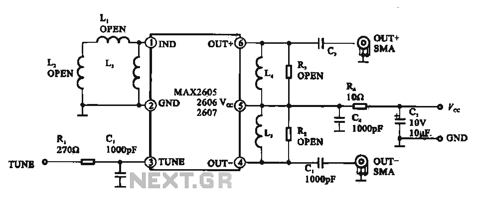
A low phase noise voltage-controlled oscillator circuit is presented, specifically integrated within the MAX2605-2609 voltage-controlled oscillator series. The circuit features a tuning voltage control terminal, allowing for adjustable oscillation frequency through a DC voltage input. The output of the...
This is the schematic diagram of a DC motor speed controller circuit. The circuit utilizes two oscillators/timers that are configured as a Pulse Width Modulator (PWM). The timer chip used in this circuit is a dual NMOS timer/oscillator. The DC...
The electric fence control circuit includes a +6 V power supply circuit, a high-voltage output circuit, a trigger control circuit, an alarm circuit, and a protection circuit. The +6 V power supply circuit consists of a power control button...
This circuit illustrates a remote control circuit diagram using RF technology without the use of a microcontroller. Features include a simple remote control circuit that operates via radio frequency. The remote control circuit operates by transmitting signals through radio waves,...
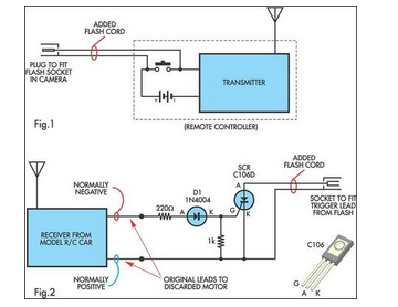
A radio-controlled electronic flash is an essential tool in any photographer's kit. Professionals frequently utilize them, such as wedding photographers. A radio-controlled electronic flash system typically consists of a transmitter and one or more receivers. The transmitter, often mounted on the...
Warning: include(partials/cookie-banner.php): Failed to open stream: Permission denied in /var/www/html/nextgr/view-circuit.php on line 713
Warning: include(): Failed opening 'partials/cookie-banner.php' for inclusion (include_path='.:/usr/share/php') in /var/www/html/nextgr/view-circuit.php on line 713