
Simple Infrared Control Extender
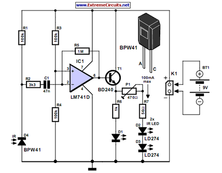
Infrared (IR) remote controls operate by emitting modulated infrared light signals that are detected by a photodiode or phototransistor in the receiving device. The common components of an IR remote control system include the remote control transmitter, which contains an infrared LED, and the receiver, which typically consists of an IR sensor and associated circuitry for decoding the received signals.
To extend the range of an IR remote control, several methods can be employed. One approach is to enhance the transmitter's output power by using a more efficient infrared LED or by incorporating a lens to focus the emitted light. Additionally, the receiver can be improved by using a more sensitive photodiode or phototransistor, which can detect weaker signals from a greater distance.
Another method to extend the range is to utilize a series of IR repeaters. An IR repeater receives the signal from the remote control and retransmits it, effectively amplifying the signal over longer distances or through obstacles such as walls. These repeaters can be wired or wireless, depending on the application requirements.
In summary, extending the range of infrared remote controls involves improving the transmission and reception components, as well as utilizing repeaters to ensure reliable signal transmission over greater distances. This can enhance user experience and convenience in operating various consumer electronic devices.Lots of consumer electronic equipment like TV sets, VCRs, CD and DVD players employs infrared remote control. In some cases, it is desirable to extend the.. 🔗 External reference
Related Circuits
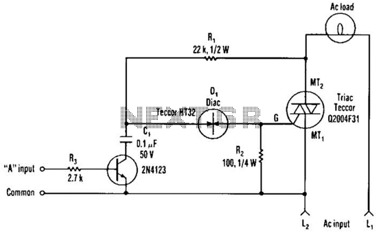
The single transistor connected between the capacitor and the common side of the AC line allows a logic-level signal to control this TRIAC power circuit. Resistor R2 prevents false triggering of the TRIAC by the trickle current through the...
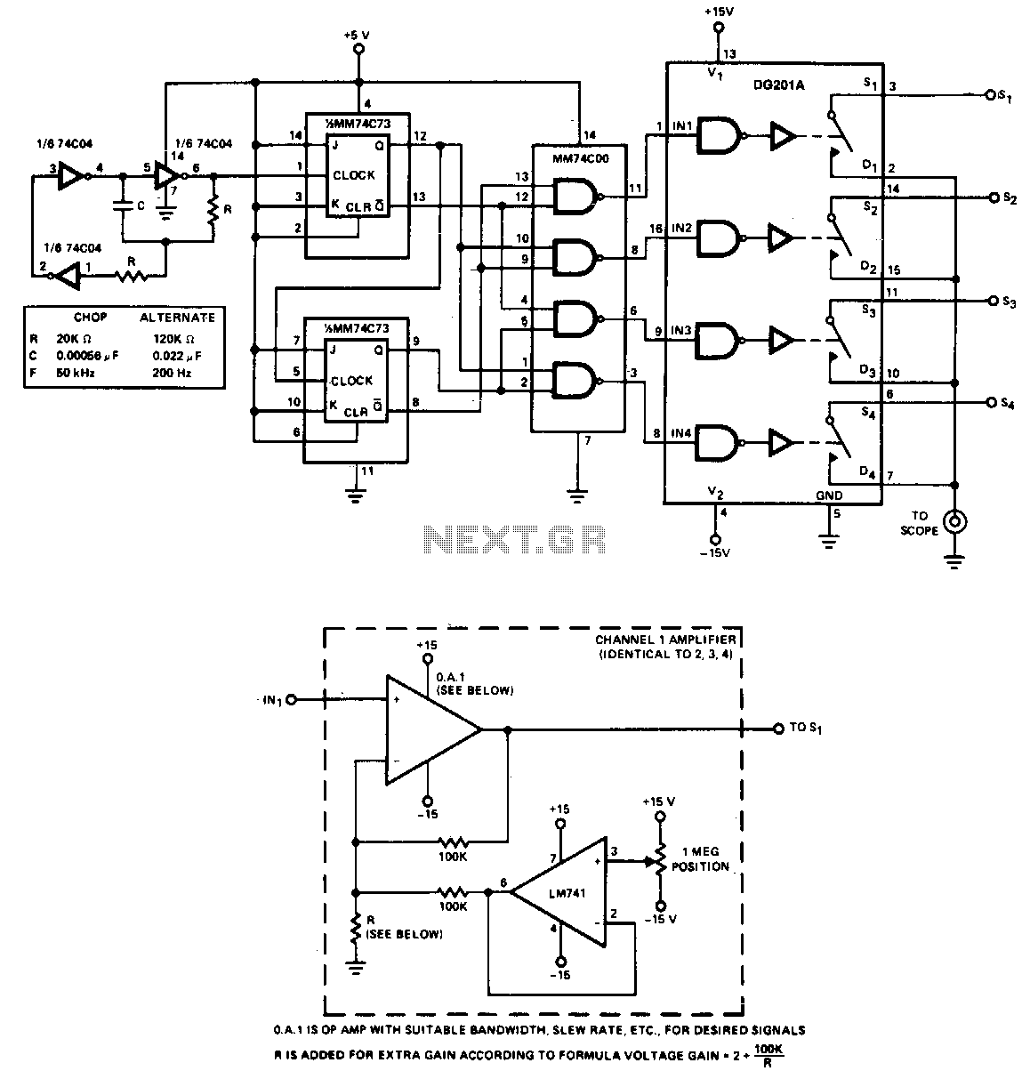
The adapter enables the simultaneous display of four inputs on a single trace oscilloscope. For low-frequency signals, specifically those below 500 Hz, the adapter operates in chop mode at a frequency of 50 kHz. Although the clock can be...
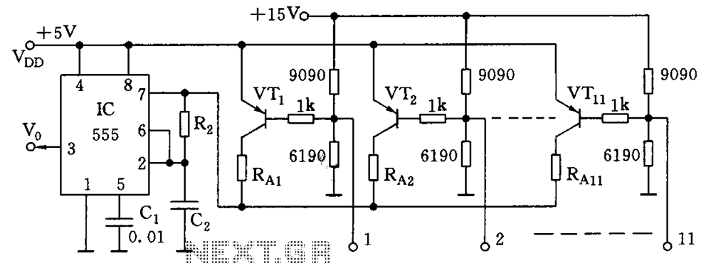
As illustrated in the figure, the base bias circuit for transistors VT1 to VT11 is designed to accept binary data, where a high level represents 1 and a low level represents 0. This configuration allows for 2048 combinations of...

The AVR 8-Bit RISC microcontroller from Atmel is a widely used microcontroller. This microcontroller integrates EEPROM, RAM, an Analog to Digital converter, numerous digital input and output lines, timers, UART for RS-232 communication, and various other features. An article...
This project represents an older design that has likely been replaced by a newer version. Nevertheless, it remains a functional design and can be beneficial for homebrew synthesizer enthusiasts. It should be noted that the majority of these designs...
This document discusses a do-it-yourself alarm system utilizing the PIC18F452 microcontroller. It is a highly engaging project, although the schematic is quite complex. The project employs three main components to create the personal alarm system. The infrared (IR) proximity...
Warning: include(partials/cookie-banner.php): Failed to open stream: Permission denied in /var/www/html/nextgr/view-circuit.php on line 713
Warning: include(): Failed opening 'partials/cookie-banner.php' for inclusion (include_path='.:/usr/share/php') in /var/www/html/nextgr/view-circuit.php on line 713