
Infrared circuits for remote control

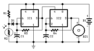
Infrared remote control systems utilize a transmission method based on modulated infrared light to convey data wirelessly. The core of the transmitter circuit consists of an oscillator capable of generating a square wave signal within a frequency range of 32 kHz to 56 kHz. This oscillator is typically implemented using a 555 timer IC or a microcontroller configured to produce a stable frequency output.
The modulating signal, which is a TTL-level voltage, is responsible for controlling the oscillator's operation. When the modulating signal is high, the oscillator is activated, producing a square wave that is then transmitted as infrared light through an LED. The modulation technique employed is On-Off Keying (OOK), where the presence of the infrared light represents a binary '1', and its absence represents a binary '0'. This method allows for the transmission of digital signals at speeds between 1000 to 4000 bits per second.
On the receiver end, the system typically includes a photodiode or phototransistor that detects the modulated infrared light. The photodiode converts the incoming light signal back into an electrical signal, which is then processed by a demodulator circuit. This circuit is designed to filter out the carrier frequency (32-56 kHz) and extract the original digital signal (1-4 kHz) for further processing, such as decoding the data and executing commands.
To ensure reliable communication, the design may incorporate additional components such as resistors, capacitors, and amplifiers to optimize the performance of both the transmitter and receiver circuits. The overall system is often housed in a compact enclosure to facilitate ease of use and portability, making infrared remote controls a practical solution for various applications in consumer electronics.Infrared remote controls are using a 32-56 kHz modulated square wave for communication. These circuits are used to transmit a 1-4 kHz digital signal (OOK modulation) through infra light (this is the maximum attainable speed, 1000-4000 bits per sec). The transmitter oscillator runs with adjustable frequency in the 32-56kHz range, and is being turned ON/OFF with the modulating signal, a TTL voltage on the MOD input.
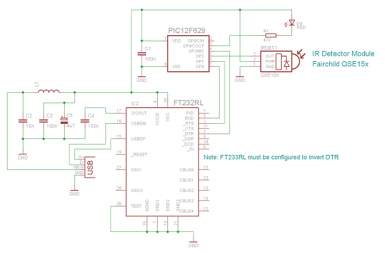
On the receiver side a photodiode takes up the signal. 🔗 External reference
Related Circuits
R2 47Ω 1/4W Resistor, D1 LED (any dimension, shape, and color), Q1 Infrared Photo Transistor (any inexpensive type), Q2 BC327 45V 800mA PNP Transistor, SW1 SPST Toggle or Slide Switch (optional, see note), B1 3V Battery (2 x 1.5V...
The IR Widget operates in a manner that ensures compatibility with modern multitasking operating systems. It can determine the carrier frequency and demodulate the carrier in both the digital and analog domains. The captured information can be utilized to...
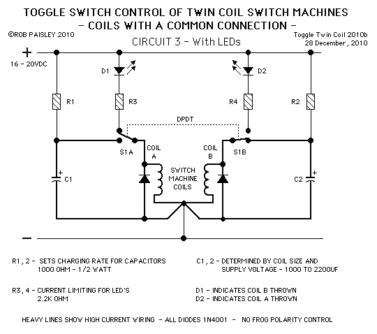
These circuits allow an ON-ON type DPDT toggle switch to control a twin coil switch machine motor. The handle of the switch can then be used to indicate the route selected. The circuits are also able to control LEDs...
This high-Q notch filter operates at 60 Hz and is based on the "Twin-T" design. It creates a significant notch in the response curve at approximately 59.7 Hz, effectively eliminating 60 Hz hum and noise from audio recordings or...

The TPS6420x controller is designed to operate from one to three series-connected cells or from a 3.3 V or 5 V supply obtained from a USB port. At its output, it can produce 3.3 V at 2 A, suitable...

This topic will be locked and will display all of the circuits and some photos of the devices being worked on in the Joule Thief topic. This process will take some time, so patience is appreciated. If any errors...