
IR Remote-Control Checker
This circuit is designed for dual functionality: testing infrared remote controls and managing water levels. The first section of the circuit, which includes the infrared photo transistor (Q1) and LED (D1), operates by detecting infrared signals emitted from remote controls. When a button is pressed on the remote, the emitted infrared light is detected by Q1, causing the LED to flash. This simple circuit is powered by a 3V battery comprised of two AA or AAA cells connected in series, ensuring portability and ease of use for hobbyists.
The second part of the circuit involves water level detection and control. The two steel rods act as sensors that detect the water level in a tank. The shorter rod serves as a high-water sensor, while the longer rod serves as a low-water sensor. The IC1 component, a quad 2-input NOR gate, processes the signals from these sensors to control the operation of a relay (RL1) and, consequently, a pump. The relay is responsible for switching the pump on and off based on the water level detected by the sensors.
The circuit's design ensures that the pump operates efficiently by maintaining the water level within desired limits. The optional SPDT switch (SW1) allows for flexibility in operation, enabling the user to choose between filling and emptying the reservoir. This adaptability makes the circuit suitable for various applications, including aquariums, water tanks, and automated irrigation systems. The inclusion of additional components, such as resistors (R3 and R4) and diodes (D2), ensures stable operation and protection against voltage spikes, enhancing the reliability of the circuit in practical scenarios.
Overall, this schematic represents a versatile and user-friendly solution for both testing infrared devices and managing water levels, making it an invaluable tool for electronics enthusiasts and practical applications alike.R2_47R 1/4W Resistor D1_LED (Any dimension, shape and color) Q1_Infra-red Photo Transistor (Any cheap type) Q2_BC327 45V 800mA PNP Transistor SW1_SPST Toggle or Slide Switch (Optional, see Note) B1_3V Battery (2 x 1. 5V AA, AAA or smaller type Cells in series) A very simple device allowing a quick check of common Infra-red Remote-Controls can be us
eful to the electronics amateur, frequently asked to repair or test these ubiquitous devices. A reliable circuit was designed with a handful of components: the LED will flash when any of the Remote-Control pushbuttons will be pressed. The side of the Remote-Control bearing the IR emitting diode(s) must be directed towards the Photo Transistor (Q1) of the checker circuit: maximum distance should not exceed about 20 - 25cm.
Current drawing of the circuit is less than 1mA when the LED illuminates and 0mA when no signal is picked-up by the Photo Transistor: therefore, SW1 can be omitted. R3_10K 1/4W Resistor R4_1K 1/4W Resistor D1_LED any type and color D2_1N4148 75V 150mA Diode IC1_4001 Quad 2 Input NOR Gate CMos IC Q1_BC337 45V 800mA NPN Transistor SW1_SPDT Toggle or Slide Switch (Optional) RL1_Relay with SPDT 2A @ 230V switch Coil Voltage 12V - Coil resistance 200-300 Ohm Two steel rods of appropriate length The shorter steel rod is the "water high" sensor, whereas the longer is the "water low" sensor.
When the water level is below both sensors, IC1C output (pin #10) is low; if the water becomes in contact with the longer sensor the output remains low until the shorter sensor is reached. At this point IC1C output goes high, Q1 conducts, the Relay is energized and the pump starts operating.
Now, the water level begins to decrease and the shorter sensor will be no longer in contact with the water, but IC1C output will be hold high by the signal return to pin #5 of IC1B, so the pump will continue its operation. But when the water level falls below the longer sensor, IC1C output goes low and the pump will stop. SW1 is optional and was added to provide reverse operation. Switching SW1 in order to connect R3 to pin #11 of IC1D, the pump will operate when the reservoir is nearly empty and will stop when the reservoir is full.
In this case, the pump will be used to fill the reservoir and not to empty it as in the default operating mode. The circuit can be used also with non-metal tanks, provided a third steel rod having about the same height of the tank will be added and connected to the circuit`s negative ground.
🔗 External reference
Related Circuits
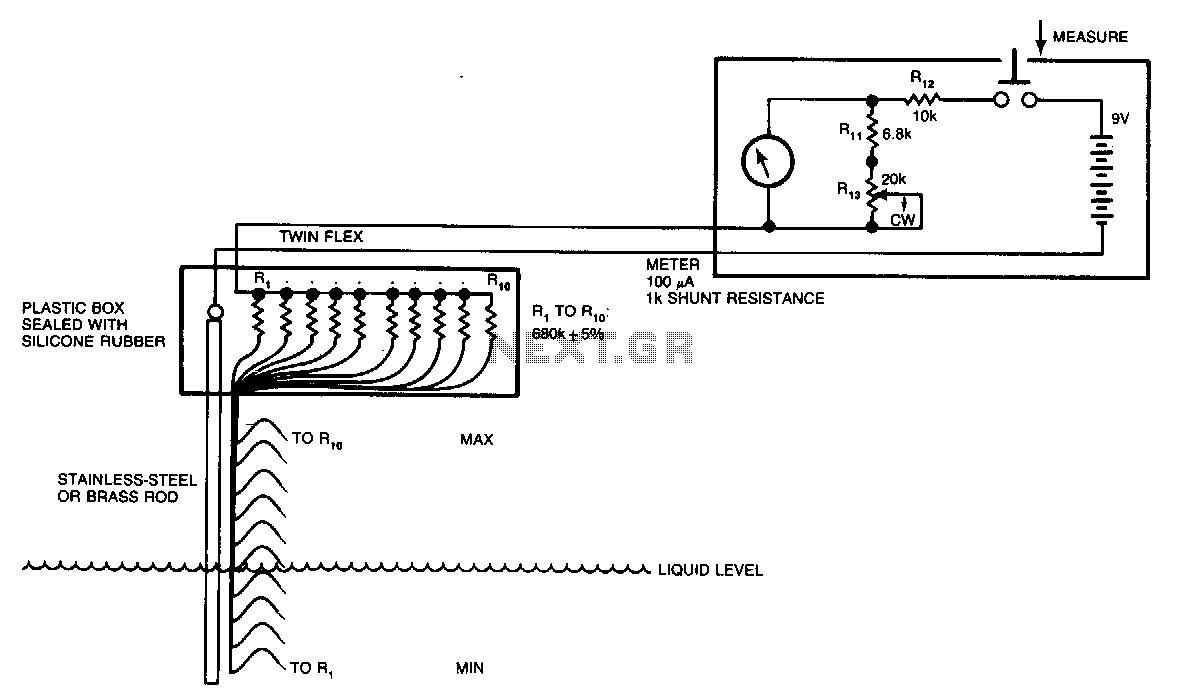
Although many circuits utilize the varying-capacitance method for measuring liquid levels, this straightforward resistive circuit is significantly easier to construct. Even a tank containing a liquid, such as water, has sufficient conductive salts in solution for this method to...
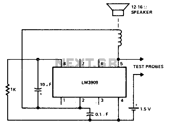
Differences between shorts, coils, and a few ohms of resistance. More: can be heard. Short circuits, inductive coils, and resistive components each play distinct roles in electrical circuits. A short circuit occurs when there is an unintended low-resistance connection between...
These units can be useful as a short-range, single-channel remote-control. When the pushbutton in the transmitter circuit is briefly activated, the LED D1 in the receiver illuminates and an optional beeper or relay can be operated. Circuit operation is...
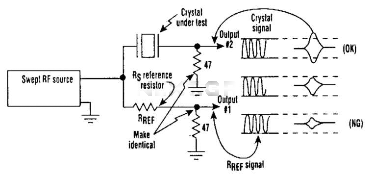
Occasionally, microprocessors and microcomputers may not be compatible with certain microprocessor crystals. Many data sheets for microprocessors specify maximum values for a crystal's equivalent series resistance (Rs), which may not be met by some crystals marketed for use with...
This document serves as a compilation of design notes, providing practical details as construction progresses, along with some photographs that will be included in due course. Currently, it functions as a progress report, blending immediate plans with actual construction,...
This circuit enables audio monitoring of a remote location, functioning as both a room monitor and a baby alarm. It can be powered by a 12-volt battery or a mains power supply. The interconnection utilizes three wires, allowing for...