
batteries charger and psu circuit
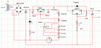
The circuit design incorporates a battery charger section that is optimized for charging lithium-ion or nickel-metal hydride batteries. The charger utilizes a linear voltage regulator or a switching regulator to maintain a stable 5V output. This section typically includes components such as a transformer (if AC input is used), rectifiers to convert AC to DC, and filtering capacitors to smooth the output voltage. Protection features, such as overvoltage and overcurrent protection, may also be integrated to ensure safe operation during the charging process.
The regulated power supply section of the circuit employs an adjustable voltage regulator, which can be implemented using a variable resistor (potentiometer) in conjunction with a linear voltage regulator, such as the LM317. This allows the user to set the output voltage anywhere between 2V and 9V, depending on the requirements of the connected load. The circuit may include additional filtering capacitors to reduce noise and improve voltage stability, along with heat sinks to manage thermal dissipation from the voltage regulator.
Overall, this circuit provides a versatile solution for charging batteries and supplying variable voltage to various electronic devices, making it suitable for a wide range of applications in both hobbyist and professional settings.There are two parts in this circuit, ie the battery charger with a fixed output voltage, which is 5VDC. Another part is the regulated power supply that can be regulated output voltage between 2-9 volts. 🔗 External reference
Related Circuits
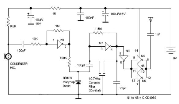
Logic Gates FM Transmitter Circuit Electronic Circuit Schematic Wiring Diagram. The FM transmitter circuit utilizing logic gates is a fundamental electronic design that operates by modulating a carrier frequency with an audio signal. This circuit typically consists of various logic...
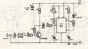
This infrared transmitter utilizes pulse width modulation (PWM). The transmitter is equipped with an LM567 tone decoder circuit. An audio signal (at least 50 mV peak-to-peak) is amplified with transistor T1 and subsequently used to modulate IC1. The frequency...
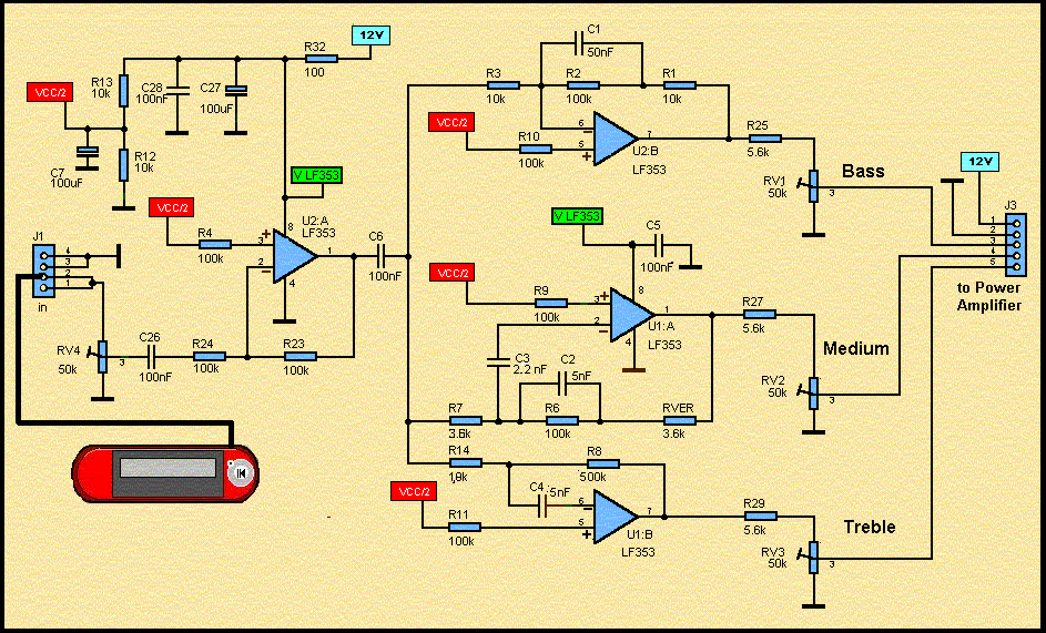
These accessories are low-cost, high-speed, bifet-input operational amplifiers utilizing internally compensated voltage (BI-FET II technology). They require low supply voltages while offering a wide gain bandwidth product and fast slew rate. Additionally, well-matched high voltage JFET input devices accommodate...
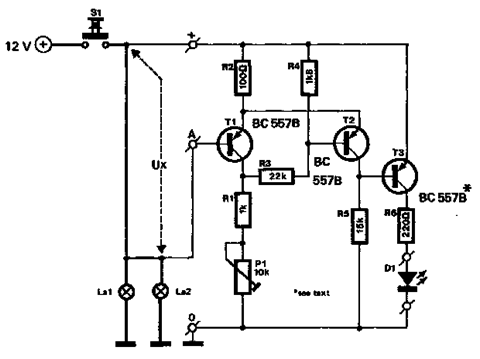
The circuit described below monitors the car's brake lights and indicates their operational status using a 12V light-emitting diode (LED). This functionality can prevent fines for driving with defective brake lights and enhance road safety. The monitor relies on...
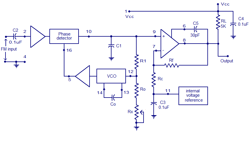
A simple PLL FM demodulator circuit using the IC XR2212 is presented. The XR2212 is a highly stable, monolithic PLL (phase-locked loop) IC specifically designed for communication and control system applications. It operates within a frequency range of 0.01...
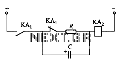
To fulfill the requirements of a control loop, it is often necessary to utilize an electromagnetic relay or a transistor relay to either accelerate or delay an action, thereby forming an acceleration or delay circuit. The circuit depicted in...