
infrared detector circuit using pid20
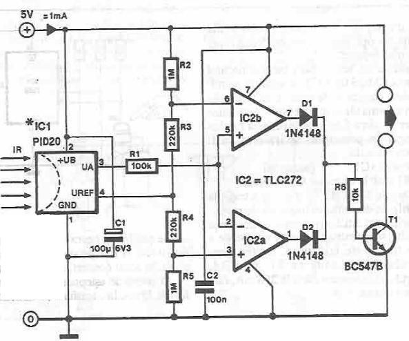
The infrared detector circuit operates on the principle of detecting variations in thermal radiation emitted by objects in its vicinity. The PID20 integrated circuit serves as the core of the detection mechanism, converting thermal energy into a measurable electrical signal. The output from the PID20 is routed to pin 3, where it is subjected to comparison against a reference voltage. This reference voltage, established by the voltage divider formed by resistors R2, R3, R4, and R5, ensures that the circuit can accurately detect changes in temperature.
In practical applications, the circuit can be used in security systems, occupancy detection, or temperature-based automation. The operational amplifiers IC2a and IC2b are configured to monitor the output signal from the PID20. When the detected thermal signal exceeds the reference threshold, the comparator IC2a will trigger. Conversely, if the signal falls below the reference threshold, comparator IC2b will activate. This dual comparison mechanism allows for precise detection of both increases and decreases in temperature.
Transistor T1 acts as a switching element that can control a load based on the output from the comparators. When activated, T1 can turn on alarms, lights, or other devices, providing a practical response to the detected thermal changes. The design of the circuit emphasizes stability and responsiveness, making it suitable for various applications where infrared detection is essential.
Overall, this infrared detector circuit exemplifies a straightforward yet effective design for monitoring thermal variations in the environment, leveraging the capabilities of integrated circuits and operational amplifiers for enhanced performance and reliability.This infrared detector circuit is designed using the PID20 integrated circuit manufactured by Siemens (which converts thermal radiation into electrical impulses), an operational amplifier and a few electronic components. The output signal at pin 3 is compared with a reference voltage equal to half the supply voltage. Reference voltage is taken fro m the voltage divider R2-R3-R4-R5. When approaching an object warmer than the surrounding environment, or to remove an object colder than the environment, the output voltage increases. Variation of the sensor output will be compared, the IC2a and IC2b, located voltage of 0. 5 V under and over voltage reference respectively. Depending on the output, one of the comparators basculate and activates T1. 🔗 External reference
Related Circuits

A negative temperature coefficient thermistor is utilized as the temperature sensing element (Rt). The circuit includes a resistor (Ri), a resistor (Rs), a potentiometer (RP), and the thermistor (R) to form a temperature bridge. A differential amplifier is created...
This document details the AT Keyboard Interface and AT Keyboard Protocols. It includes an example of a Keyboard to ASCII decoder utilizing a 68HC705J1A microcontroller. The AT Keyboard Interface is a standard communication protocol used primarily in personal computers to...
This simple and inexpensive circuit built around a popular CMOS hex inverter IC CD4069UB offers four sequential switching outputs that may be used to control 200 LEDs (50 LEDs per channel), driven directly from mains supply. Input supply of...

A high-quality preamplifier with tone controls consisting of three circuits. The NE5532 is chosen as the main integrated circuit due to its ultra-low noise properties, making it a popular choice in fine audio applications. Although these circuits are older...

The circuit requires a 15-volt power supply and employs a precision operational amplifier, CA3193 BiMOS, to amplify the generated signal by more than 500 times. Three 22-megohm resistors are utilized to ensure a large-scale output in the event of...
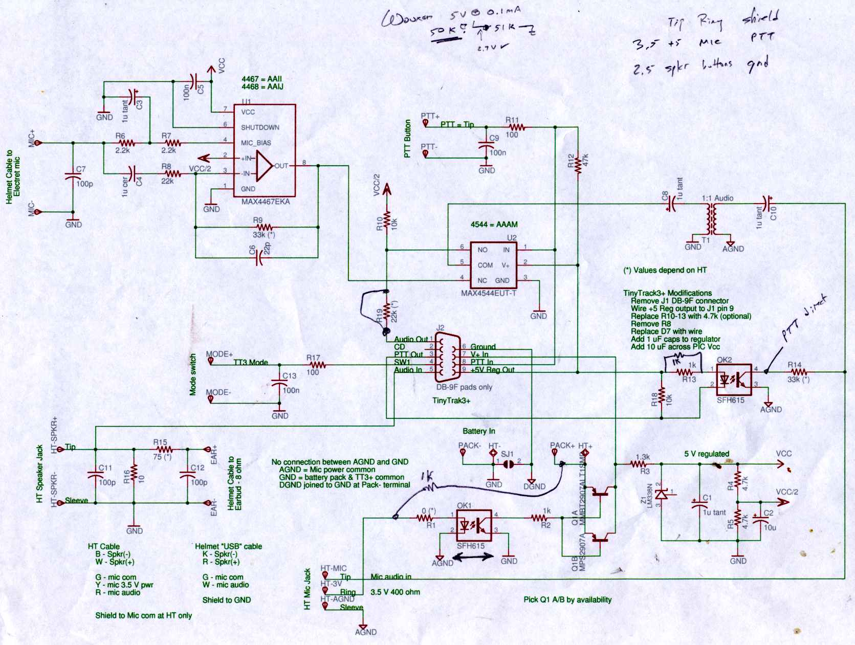
Connect the Byonics TinyTrak 3+ GPS modem, helmet earbud/mic, and external battery pack to the Z-1A, which is incompatible with the Wouxun. The KG-UV3D utilizes the Kenwood HT interface with a single ground for mic, speaker, and PTT functions,...
Warning: include(partials/cookie-banner.php): Failed to open stream: Permission denied in /var/www/html/nextgr/view-circuit.php on line 713
Warning: include(): Failed opening 'partials/cookie-banner.php' for inclusion (include_path='.:/usr/share/php') in /var/www/html/nextgr/view-circuit.php on line 713