
Over-temperature alarm circuit
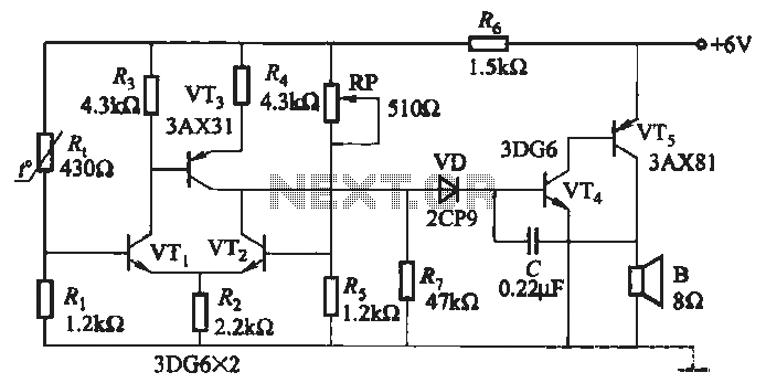
The circuit operates on the principle of a negative temperature coefficient (NTC) thermistor, which decreases its resistance as temperature increases. This characteristic is utilized in the temperature sensing element (Rt) to provide a variable resistance that is proportional to the ambient temperature. The combination of resistors (Ri and Rs) and the potentiometer (RP) establishes a temperature-sensitive voltage divider, which is critical for the temperature bridge configuration.
The differential amplifier, constructed with transistors (VT1 and VT2), amplifies the voltage difference generated by the temperature bridge. This amplification is essential for precise temperature measurements and enhances the sensitivity of the circuit. The output of the differential amplifier is then fed into the output stage, which consists of transistor (VT3) and a diode (VD), forming a critical part of the output circuit.
The audio oscillator is formed using transistor (VT4) along with capacitor (C), which generates an audio frequency signal based on the temperature readings. The oscillation frequency can be adjusted via the potentiometer (RP), allowing for customization of the temperature setting according to specific application requirements. This flexibility is particularly useful in applications where precise temperature control is necessary.
Overall, this circuit exemplifies a sophisticated approach to temperature sensing and control, integrating various electronic components to achieve a reliable and adjustable output based on temperature variations.It uses a negative temperature coefficient thermistor for temperature sensing element Rt. By the resistor Ri, Rs, , potentiometer RP and thermistor R. Composition temperature bridge; by the transistor VTi, VT2 constituting the differential amplifier; by the transistor and diode VD composition VTs output circuit; by the transistor VT4, VTs and capacitor C etc. audio oscillator. Adjustment potentiometer RP, can change the temperature setting.
Related Circuits
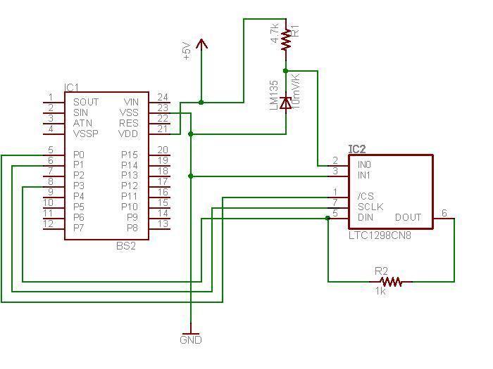
The schematic diagram illustrates the temperature sensor that is set to be launched. The LM135 sensor, functioning as a Zener diode, is connected via a foot-long cord to the circuit through a plug. This design allows the sensor to...

Digital Command Control (DCC) provides significant advantages over traditional DC analog control systems, primarily due to its simplified wiring. DCC enables the individual control of multiple locomotives on the layout without requiring electrical isolation of track sections. The main...
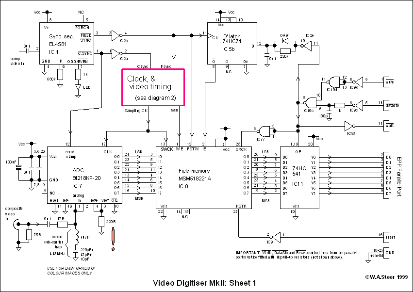
A video digitizer, also known as a frame grabber, captures still picture frames from a television set, video camera, or video recorder, and transmits them to a computer for display, storage, or manipulation. This document outlines the Mark II...
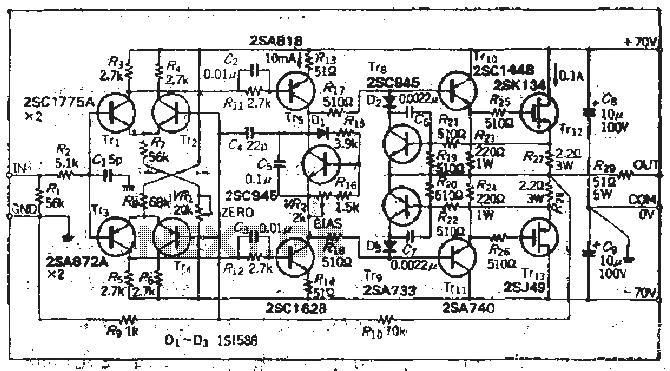
The south circuit consists of four parts, arranged in descending order: an NPN transistor dynamic garbage device (T1), a PNP transistor differential amplifier (T2, T3) forming a double differential circuit, two balanced output amplifiers with opposite phase, and a...
Hens require adequate illumination to increase egg production rates. To counteract the reduced winter sunlight, poultry farms commonly utilize artificial lighting in coops. For instance, the circuit depicted in Figure 297 can automatically provide light at night. The light...
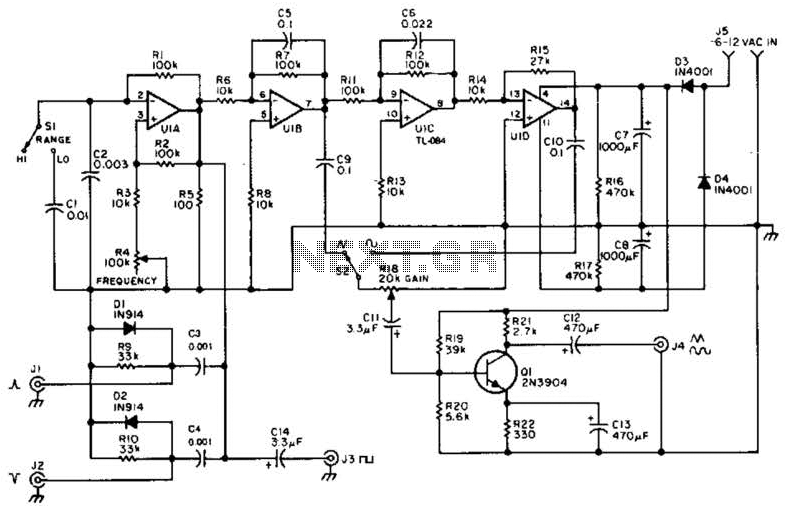
A quad op-amp serves as the core component of this function generator. U1A produces a square wave, which is outputted to J8. J1 and J2 are pulse outputs derived from differentiating the square wave. The integrator U1B creates a...
Warning: include(partials/cookie-banner.php): Failed to open stream: Permission denied in /var/www/html/nextgr/view-circuit.php on line 713
Warning: include(): Failed opening 'partials/cookie-banner.php' for inclusion (include_path='.:/usr/share/php') in /var/www/html/nextgr/view-circuit.php on line 713