
gps voice interface for wouxun kg uv3d circuit

The circuit configuration involves integrating the Byonics TinyTrak 3+ GPS modem with a helmet-mounted earbud/mic and an external battery pack to the Z-1A radio system. The incompatibility with the Wouxun model necessitates a careful redesign of the connection scheme. The KG-UV3D's Kenwood HT interface, which employs a single ground for microphone, speaker, and push-to-talk (PTT) functions, simplifies the design by eliminating the need for galvanic isolation. Consequently, the removal of optoisolators and audio transformers is planned to streamline the circuit.
The power supply characteristics differ between the IC-Z1A and KG-UV3D. The IC-Z1A provides 3.5 V through a 400-ohm resistor, delivering 6 mA to the optoisolator LED, whereas the KG-UV3D supplies 5 V through a 50 k-ohm resistor, which translates to 100 µA. This voltage level is anticipated to be adequate to drive a logic-gate MOSFET, facilitating the switching of power via a PNP transistor. Currently, the control of interface power is managed by disconnecting the external battery, as the radio is powered by its own snap-on lithium-ion battery.
The PTT functionality has been revised to utilize a dedicated logic wire, moving away from the previous multiplexing method, which combined DC current with the audio line. A modification on the OK2 board was implemented as a straightforward solution to accommodate this change. However, it is suggested that the TT3 PTT output line may have the capacity to directly manage the PTT requirement.
Audio performance is a critical component of this setup, with the KG-UV3D necessitating additional microphone gain that is not incorporated into the current modifications. Furthermore, an increase in output from the TinyTrak 3+ is also required. The calibration process for the TT3, previously conducted for the IC-Z1A, is expected to be a labor-intensive task if repeated.
An analog multiplexer is recommended for audio signal switching to mitigate the interference of machine noise with voice communications. Due to constraints in mounting options on the radio and the inability to control the interface power in a mounted configuration, the components are currently secured to the side of the battery pack holding the radio. This temporary solution is not viable for long-term use. There is a concern that the KG-UV3D may introduce additional radio frequency interference (RFI) into the microphone circuit, as the current placement is the only configuration that avoids audio dropouts during voice transmissions. Future adjustments will be essential once a more permanent housing solution is implemented for the components on the radio.Connect the Byonics TinyTrak 3+ GPS modem, the helmet earbud/mic, and the external battery pack to the Z-1A doesn`t work with the Wouxun. It`s all different: Because the KG-UV3D uses the Kenwood HT interface with a single ground for mic, speaker, and PTT functions, there`s no need for galvanic isolation; all the optoisolators & the audio transformer will
Go Away when I rebuild it. One distressing change: the IC-Z1A mic power was 3. 5 V behind 400 © = 6 mA into an optoisolator LED, but the KG-UV3D puts 5 V behind 50 k © = 100 µA into a dead short. I think the voltage will suffice to drive a logic-gate MOSFET to switch the power through a PNP transistor, but, for the moment, I hotwired OK1 and control the interface power by unplugging the external battery.
The radio runs from its own snap-on Li-Ion pack. The PTT now has a separate logic wire and is no longer multiplexed as a DC current on the audio line. The hack on OK2 was the easiest way to make that happen on the existing board, but the TT3 PTT Out line can probably drive the PTT directly.
I`m not happy with the audio levels; the KG-UV3D requires more mic gain (which change doesn`t appear in the mods) and more TT3 output. Having tediously calibrated the TT3 for the IC-Z1A, I`m not looking forward to doing that again. I still like using an analog multiplexer to switch the audio signal, though, because it doesn`t mix the machine noise with the voice transmissions.
There being no way to mount the box on the radio and no way to control the interface power if I did, I simply lashed it to the side of the pack holding the radio behind the seat. Obviously, that can`t last forever I think the KG-UV3D stuffs more RFI into the mic circuit, because that box is now in the only position that doesn`t result in weird voice audio dropouts.
Given the precarious nature of the thing, though, I must look again after getting it in a box on the radio. 🔗 External reference
Related Circuits
The automatic sprinkler controller circuit consists of a power supply circuit and a humidity measurement and control circuit, as illustrated in the accompanying figure. The power supply circuit includes a power transformer (T), rectifier diodes (VD1 to VD4), filter...
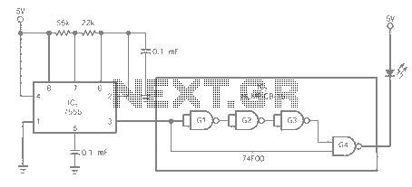
The entire series of TTL monostable multivibrators lacks sufficient speed, prompting the need for an ECL voltage swing that accommodates a wide range of small power requirements. This necessitates the use of F series circuits, which offer fast transition...
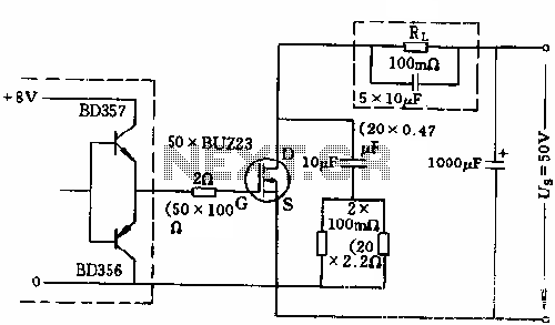
The circuit employs 50 BUZ23 field effect transistors (FETs) arranged in parallel, with a tube blocking voltage of 100V. The control power required is minimal, eliminating the risks associated with second breakdown and the positive temperature coefficient phenomenon in...
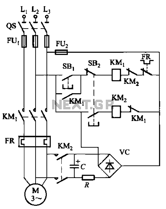
The circuit depicted in Figure 3-138 utilizes the principle of energy storage through capacitor discharge to achieve braking. The capacitance (C) and resistance (R) parameters are determined based on the size of the motor power. The capacitance (C) is...
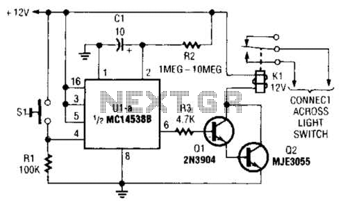
A normally open pushbutton switch (SI) provides a positive input pulse to pin 4 of U1, activating the integrated circuit (IC). The output from U1 at pin 6 delivers base-drive current to a Darlington pair consisting of Q1 and...
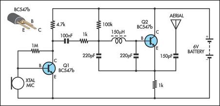
This AM transmitter is designed for simplicity, featuring an untapped inductor with a single winding. The inductor can be easily sourced as a standard RF choke, such as the Jaycar Cat LF-1536. To minimize the circuit size, a conventional...