
Infrared Light Controled Switch

The remote-controlled relay circuit operates by using a light-sensitive component as the primary sensor. Depending on the choice of D1, the circuit can be configured to respond to different types of light signals. For instance, if a phototransistor is used, it will react to ambient light changes, while an LDR (Light Dependent Resistor) will respond to varying light levels. An infrared transistor, on the other hand, will specifically respond to infrared signals emitted by an IR remote control.
The main components of the circuit include a relay, which is responsible for switching the connected load (such as lamps), and the light-sensitive device (D1). When the appropriate light signal is detected, the relay is activated, allowing current to flow to the load. The relay's operation is crucial for isolating the control circuit from the high-power load, ensuring safe operation.
The adjustment of circuit sensitivity is facilitated by the variable resistor RV2. This component allows for fine-tuning the threshold at which the relay activates in response to the light input. By rotating RV2, the user can increase or decrease the sensitivity, allowing the circuit to function optimally in various lighting conditions or distances from the remote control.
In summary, this remote-controlled relay circuit is a versatile solution for controlling electrical devices wirelessly. Its design is straightforward, making it suitable for hobbyists and professionals alike, and it can be adapted for various applications by selecting the appropriate light sensor and adjusting the sensitivity.This circuit is simple remote controlled relay. It is able to switch lamps or other devices. D1 can be a phototransistor or LDR or an infrared transistor. circuit is controlled with an IR remote like a TV remote control (when IR transistor is used) You can change circiut sensitivity with RV2. 🔗 External reference
Related Circuits
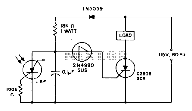
When the light incident on the LASCR is interrupted, the voltage at the anode of the 2N4990 unilateral switch becomes positive during the subsequent positive cycle of the power supply. This action triggers the switch and the C230 SCR...

This paper gives a practical example of the design of an off-line switching power supply. Factors governing the choice of a discontinuous flyback topology are discussed. The design uses a pulsed-width modulation (PWM) control scheme implemented with a Unitrode...
This Super Light Sensor responds to minute fluctuations in light levels, automatically adjusting from approximately 200 lux to 60,000 lux (from a modestly lit room to direct sunlight). It has various potential applications, such as detecting a car entering...
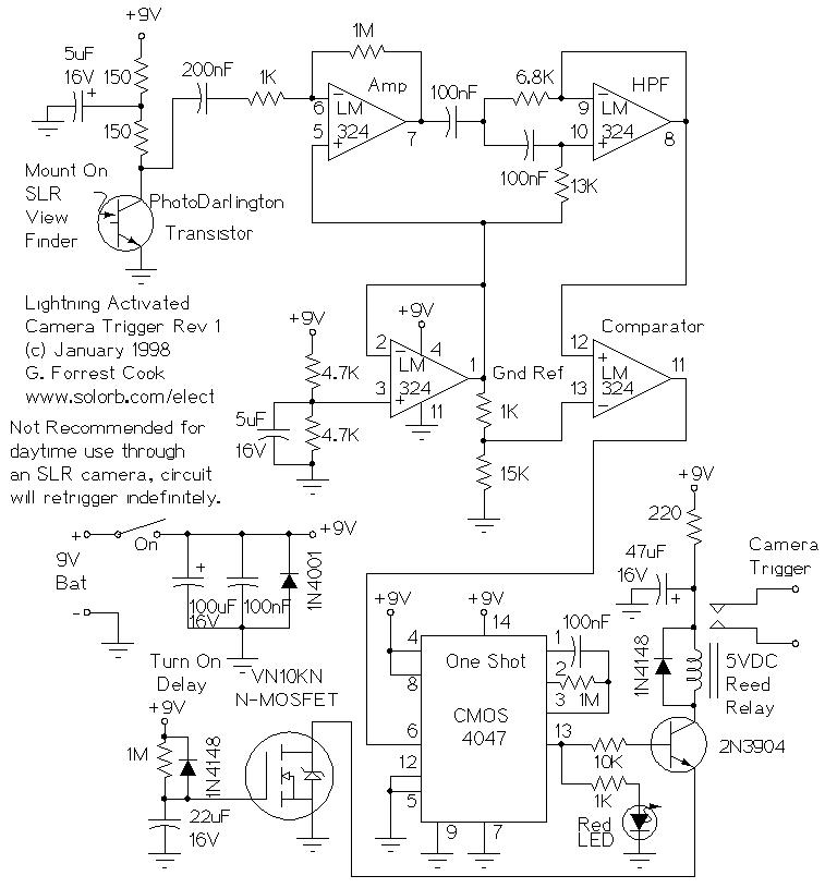
Lightning Activated Camera Shutter Trigger. This picture was taken using the circuit. This circuit is used to trigger a camera's electronic shutter circuit when a flash occurs. The Lightning Activated Camera Shutter Trigger is designed to capture images of lightning...
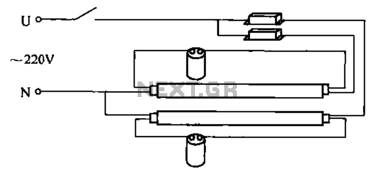
A double tube fluorescent lighting circuit is illustrated. In certain situations, a single tube light may not fulfill the lighting requirements, necessitating the use of double tube lighting. The physical installation is depicted in the circuit of a double...

FGDF-3 is a three-phase low-temperature iron plating power commutation control switch and electronic circuit. The KGDF-3 serves as a low-temperature iron plating power supply device, incorporating the characteristics of a single-phase low-temperature iron plating power supply. This design facilitates...