
Double tube fluorescent lighting circuit
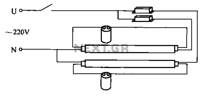
The double tube fluorescent lighting circuit operates by integrating two individual single-tube circuits into a cohesive system designed to enhance illumination levels. Each tube operates independently, allowing for a more efficient distribution of light compared to a single tube. The circuit typically includes components such as a ballast, which regulates the current flowing through the tubes, ensuring they operate at optimal efficiency while preventing flickering or overheating.
The installation of the double tube fluorescent lighting circuit involves connecting the two tubes in parallel or series, depending on the design requirements. In a parallel configuration, each tube receives the same voltage, providing uniform brightness, while in a series configuration, the voltage is divided between the two tubes, which may result in varied brightness levels.
The circuit is designed to accommodate standard fluorescent tubes, typically available in various lengths and wattages, allowing for flexibility in lighting design. Additional components may include starters, which help initiate the gas discharge process in the tubes, and switches for controlling the on/off state of the lighting system.
This type of lighting solution is commonly used in commercial and industrial settings where higher luminous output is essential for visibility and safety. The double tube fluorescent lighting circuit not only enhances brightness but also contributes to energy efficiency, making it a practical choice for extensive lighting applications. Proper installation and maintenance of this circuit are crucial to ensure longevity and optimal performance of the fluorescent tubes.Double tube fluorescent lighting circuit is shown. In some cases the need to improve twice, single-tube light can not meet the lighting requirements, double tube lighting. Phys ical installation is shown in a double tube lamp shown. Double tube fluorescent lighting circuit is a combination of two single-tube lamp circuit,
Related Circuits
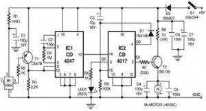
The following circuit illustrates an Infrared Toy Car Motor Controller. This circuit is based on the 4047 and 4017 integrated circuits (ICs). Features include a 16V capacitor, a 100k resistor, and the use of dual ICs. Components involved are...
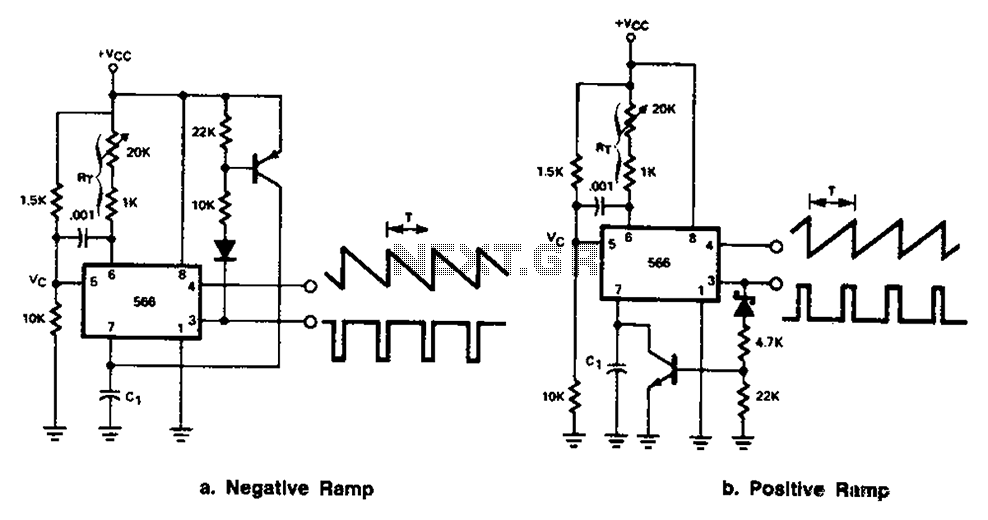
The 566 can be connected to either a positive or negative ramp generator. For a positive ramp generator, an external transistor is driven by the output pin 3. At the end of charging, C1 discharges quickly, allowing for immediate...

The lantern control circuit allows for the management of 30 outputs through an external driver circuit, specifically designed for water sports or large decorative lantern applications. The circuit features a control pulse generator, which regulates the lights, and an...
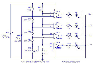
This circuit is a practical device that, when installed in a vehicle, displays the voltage of the car battery using an LED dot display. The meter circuit utilizes four comparators formed from a quad op-amp, specifically the LM324. The...
This is a design for a flashlight that two 220 V alternating lights can control. The flashlight uses only one IC. IC1a IC1c to be used for the flashing signal generation. The output of IC1c thyristor T1 is controlled,...
This circuit is an RMS-calibrated AC voltmeter that provides average readings. Removing capacitor C2 eliminates the averaging function, resulting in a precision full-wave rectifier, while removing capacitor C1 transforms the circuit into an absolute value generator. The operation of...