
Infrared Remote Control Jammer

The 555 timer is a versatile integrated circuit that can be configured in various modes, including astable, monostable, and bistable, making it suitable for a wide range of applications. In the context of a remote control jammer, the timer can be set up in an astable mode to generate a continuous square wave output. This output can then be used to interfere with the infrared (IR) signals typically emitted by remote controls.
The circuit generally consists of a 555 timer IC, resistors, capacitors, and an infrared LED. The resistors and capacitors determine the frequency of the output signal, which should be set to a value that effectively disrupts the frequency range of the remote control signals. The infrared LED emits modulated light at this frequency, which can overpower the signals sent by legitimate remote controls, thereby preventing them from functioning correctly.
Power supply considerations are also critical in this design. The circuit can be powered by a standard battery or a regulated power supply, ensuring that it operates consistently without interruptions. It is important to include a current-limiting resistor in series with the infrared LED to prevent damage due to excessive current.
In summary, the 555 timer circuit designed as a remote control jammer effectively generates a jamming signal that disrupts the operation of remote controls, making it a practical solution in scenarios where control over remote devices is necessary, such as in households with children. Proper component selection and circuit configuration are essential for achieving the desired performance and ensuring the reliability of the device.This 555 timer circuit Remote control Jammer device it s useful when we need to block someone to use the remote control (children that change frequently t.. 🔗 External reference
Related Circuits
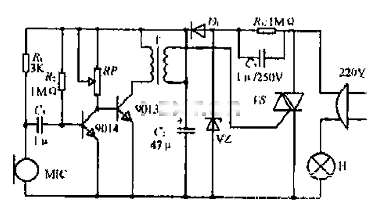
22W by Ct and R, RC Buck, rectified by n. c, filtering. vz 3V DC regulated output power, before U, V2 and MIC power supply. When the audio signal reaches the beam, the microphone MI converts acoustic energy into...

The following circuit illustrates an Automatic Loudness Control Circuit Schematic. This circuit is based on the TL072 integrated circuit. Features include various functionalities. The Automatic Loudness Control Circuit is designed to adjust audio signal levels dynamically, enhancing the listening experience...
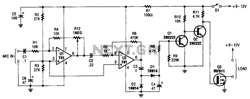
The audio-controlled switch utilizes a pair of 741 operational amplifiers, two 2N2222 general-purpose transistors, a hexFET, and several supporting components to create a circuit capable of activating devices such as a tape recorder, a transmitter, or virtually any other...
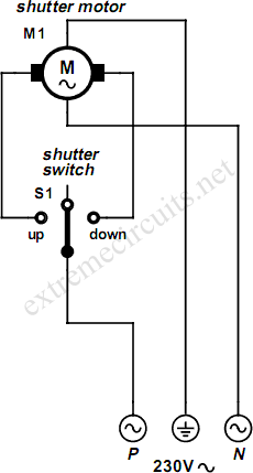
An electrically operated rolling shutter typically features a standard control panel equipped with a three-position switch: up, down, and stop. To automate the opening and closing of the shutter using a time-controlled switch, additional wiring connections are necessary. The...
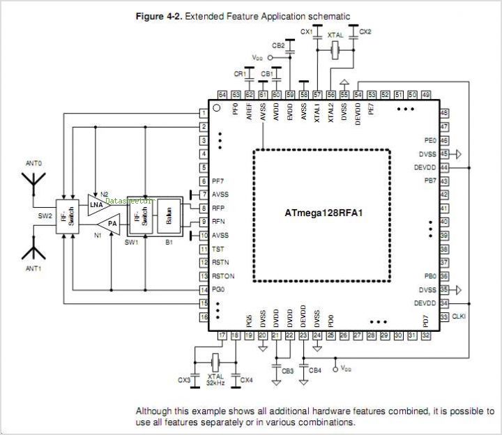
The ATR0981 is a monolithic integrated circuit (IC) produced using Atmel's advanced SiGe technology. This IC serves as a transmit and receive front-end solution, specifically designed for operation within a frequency range of 300 MHz to 500 MHz. It...
The LM1036 is a DC-controlled tone (bass/treble), volume, and balance circuit designed for stereo applications in car radios, televisions, and audio systems. The LM1036 integrates several essential audio control functions into a single chip, making it suitable for various audio...