
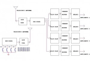
A voice-activated lights control circuit
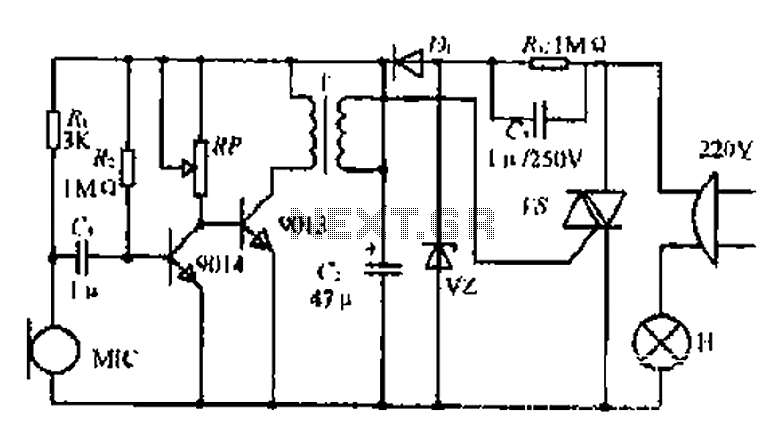
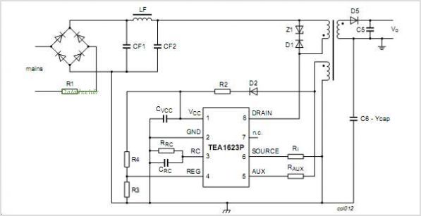
The circuit operates as a 22W power supply utilizing an RC buck converter topology, which efficiently steps down voltage while maintaining a regulated output. The rectification process is achieved through a normally closed (n.c.) configuration, followed by filtering to smooth out the rectified output, ensuring a stable 3V DC supply. This regulated output is essential for powering components labeled as U, V2, and the microphone (MIC).
The microphone (MI) plays a crucial role in the system by converting incoming acoustic signals into corresponding electrical signals. When an audio signal is detected, it triggers the discharge tube (T), which acts as a switch to control the flow of current. The output from the discharge tube is then coupled to a two-way silicon controlled rectifier (SCR), which is responsible for controlling the timing of the electrical pulses sent to the load.
The SCR is triggered by the audio signal, allowing it to conduct and control the discharge of energy to the connected load. This results in a visually appealing light effect, where the intensity and frequency of the light can vary based on the characteristics of the incoming audio signal. The entire system is designed to respond dynamically to sound, creating an interactive experience that links audio input with visual output.22W by Ct and R, RC Buck, rectified by n. c, filtering. vz 3V DC regulated output power, before U, V2 and MIC power supply. When the audio signal to the beam, the microphone MI C acoustic energy into electrical energy, and then the general discharge tube T and after coupling, can be entrusted to two-way silicon v dispatch a trigger voltage control, use audio to control thyristor conduction and cut u :, D generated so lights sparkle.
Related Circuits
The thermocouple cold junction compensation circuit and the MAX6675 converter circuit diagram form a temperature measuring system. The system utilizes a K-type thermocouple connected to the T terminals of the MAX6675, with the cold junction grounded. An 8051 microcontroller...
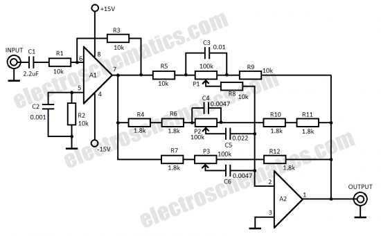
This three-band equalizer circuit functions as an active filter network for bass, mid, and high audio frequencies. It is built around the LM833 operational amplifier from National Semiconductors. The output of this three-way graphic equalizer is configured to be...
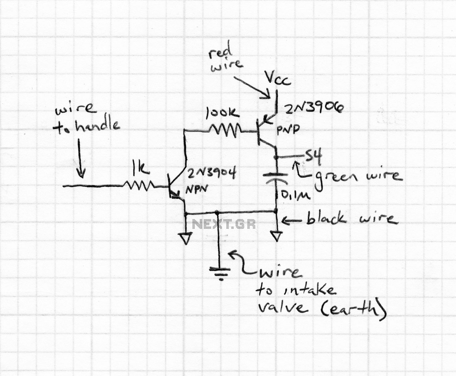
Magnetic stripe reader, electric circuit theory, logic operation. The wiring diagram does not connect the transistor in the circuit. The collector pin of the transistor connects to the tip pin of the jack. The base pin of the transistor...
This document does not aim to provide an extensive account of the integrated circuits (ICs) used in this circuit. For additional information on this topic, please refer to the "Flip-Flop Made With A LM556 Timer Chip" section and the...
This circuit illustrates a remote control circuit diagram using RF technology without the use of a microcontroller. Features include a simple remote control circuit that operates via radio frequency. The remote control circuit operates by transmitting signals through radio waves,...
The TEA5764UK is a single-chip, electronically tuned FM stereo radio that includes a Radio Data System (RDS) and Radio Broadcast Data System (RBDS) demodulator, along with an RDS/RBDS decoder. This device is designed for portable applications and features fully...
Warning: include(partials/cookie-banner.php): Failed to open stream: Permission denied in /var/www/html/nextgr/view-circuit.php on line 713
Warning: include(): Failed opening 'partials/cookie-banner.php' for inclusion (include_path='.:/usr/share/php') in /var/www/html/nextgr/view-circuit.php on line 713