
Infrared Remote Control On/Off Switch Electrical Mini Project
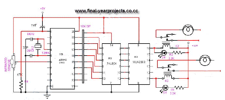
The Infrared Remote Control On/Off Switch project utilizes an 8-bit microcontroller, specifically the AT89C2051, which serves as the central processing unit for the system. The microcontroller is programmed to interpret signals received from the infrared remote control, enabling it to execute commands for switching various electrical devices on or off.
The system architecture comprises several key components: the infrared receiver module, the microcontroller, the relay driver circuit, and the relays themselves. The infrared receiver module captures the signals emitted by the remote control. These signals are then decoded by the microcontroller, which processes the command and activates the appropriate relay to control the connected appliance.
The block diagram provides a visual representation of the system's functional flow, illustrating how the input signals from the remote control are processed to produce the desired output. The circuit diagram details the connections and components used, including the power supply, microcontroller pin configuration, and relay connections.
The project also includes the source code for the AT89C2051 microcontroller, which is essential for programming the device to respond accurately to the remote control inputs. The code typically includes initialization routines, signal decoding algorithms, and relay control functions, ensuring seamless operation of the system.
This project not only demonstrates the practical application of infrared technology in home automation but also serves as an educational tool for understanding microcontroller programming, circuit design, and the integration of various electronic components.This is a good Electrical project report on Infrared Remote Control On/Off Switch and was Submitted in partial fulfillment of the requirements for the award of the degree of Bachelor of Engineering in Electrical Engineering and is used to switch on/off the Home Appliances by using a standard Remote control. The system is used to switch on/off upto six electrical devices. You can also Subscribe to FINAL YEAR PROJECT`S by Email for more such Projects and Seminar. This system uses 8 bit Microcontroller AT89C2051 and report also has block diagram and circuit diagram of Infrared Remote Control On/Off. An infra-red remote control is a component of an electronics device, most commonly a television set, used for operating the device wirelessly from a short line-of-sight distance.
Source code of microcontroller. Use this report for your reference and study only. 🔗 External reference
Related Circuits
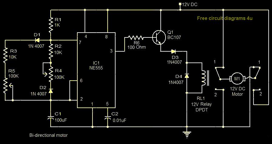
This circuit illustrates a bi-directional motor control circuit utilizing the NE555 integrated circuit (IC). Features include a 12V DC power supply, with the IC employed to control relay RL1. The bi-directional motor control circuit designed with the NE555 IC allows...

R4 prevents the output voltage from drifting toward one of the supply rails of the operational amplifier. It is understood that R4 should have a high resistance, although the reason for this is unclear. The schematic appears to be...
The automatic sprinkler controller circuit consists of a +12 V power supply circuit, a light control circuit, and an irrigation control circuit, as illustrated in the accompanying figure. The +12 V power supply circuit includes a knife switch (Q),...
The ICL7665S Super CMOS Micropower Over/Under Voltage Detector features two low-power, individually programmable voltage detectors integrated on a single CMOS chip. It typically requires 3 µA for operation and is designed for battery-operated systems and instruments that need high...
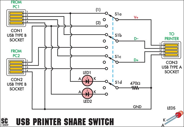
This device allows two computers to share a single USB printer or other USB devices, such as an external flash drive, memory card reader, or scanner. A rotary switch is used to select the PC that will use the...
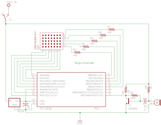
Tengu derives its name from a mythical Japanese creature known for getting into mischief. However, this Tengu is more earthly in nature. It responds to voice and sounds, changing its facial features depending on the intensity of the sound....