
Bi-Directional Motor Control CIrcuit With NE555 IC
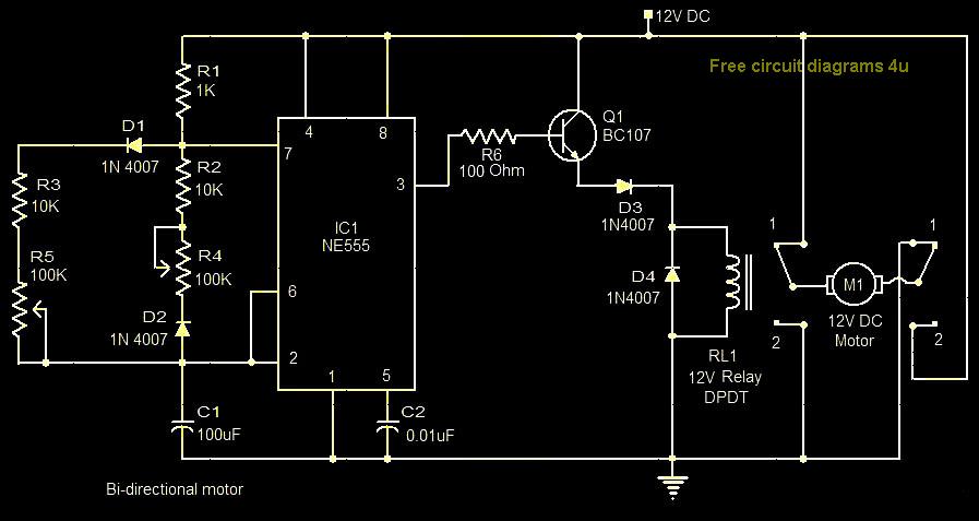
The bi-directional motor control circuit designed with the NE555 IC allows for efficient control of a DC motor's direction and speed. The circuit operates on a 12V DC power supply, which is a common voltage level for many small to medium-sized motors.
The NE555 timer IC is configured in astable or monostable mode, depending on the specific application requirements. In this setup, the NE555 generates a PWM (Pulse Width Modulation) signal, which can be adjusted to control the speed of the motor. The output from the NE555 drives a relay (RL1), which acts as a switch to control the direction of the motor.
The circuit typically includes two relays (RL1 and RL2) to facilitate the bi-directional operation. By energizing either relay, the current flow through the motor is reversed, allowing the motor to rotate in either direction. Diodes are often included across the relay coils to prevent back EMF from damaging the NE555 when the relays are de-energized.
Additional components may include resistors and capacitors that set the timing characteristics of the NE555, as well as potentiometers for adjusting the motor speed. The design is suitable for applications such as robotics, conveyor systems, and any project requiring precise motor control.
Safety features may also be integrated into the circuit, including fuses and thermal cutoffs, to protect against overcurrent conditions. Overall, this bi-directional motor control circuit is a versatile solution for various motor control applications.This circuit shows about Bi-Directional Motor Control CIrcuit With NE555 IC. Features: 12V DC power supply, IC is used to control the relay RL1 .. 🔗 External reference
Related Circuits
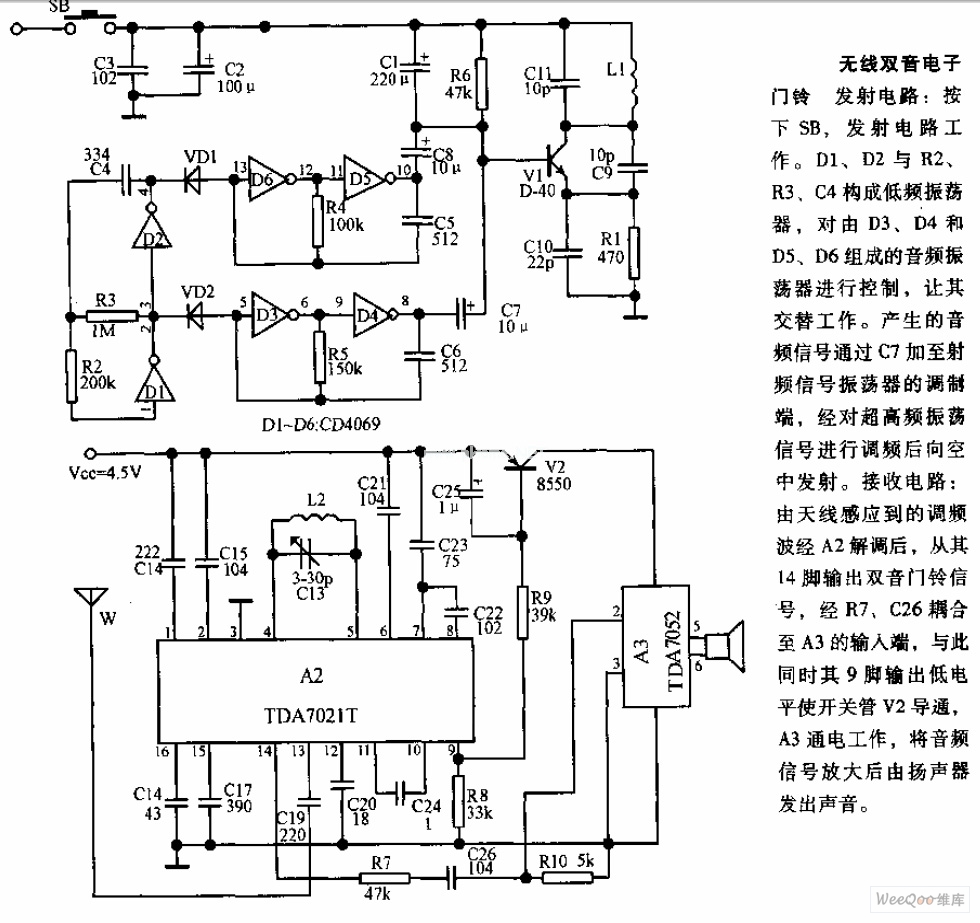
The transmitter circuit is activated by pressing the SB button. Components D1, D2, R2, R3, and C4 form a low-frequency oscillator that controls an audio oscillator made up of D3, D4, D5, and D6, allowing them to operate alternately....
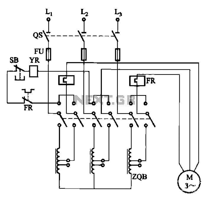
The circuit illustrated in Figure 3-47 involves a three-phase AC motor that is initially connected through a step-down autotransformer. To initiate operation, the power switch is closed, and the operating handle is pushed to the start position. Once the...

This is a 1-watt FM amplifier with an effective design that can be used to amplify an RF signal in the 88 - 108 MHz band. It exhibits high sensitivity when paired with quality RF components. The 1-watt FM amplifier...
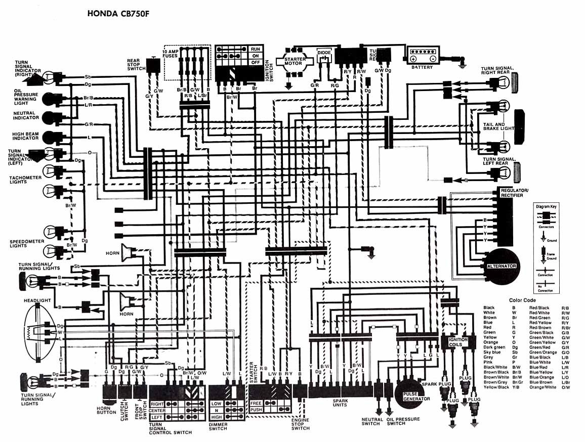
The following account presents the electrical wiring diagram for the Honda Motorcycle CB750F. It illustrates the connections between various Honda components, including the right turn signal indicator light, oil pressure warning light, neutral indicator, high beam indicator, turn signal...
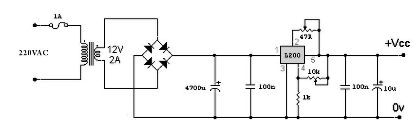
A variable power supply based on the L200 IC, where the output voltage is controlled by a 10K variable resistor. The output voltage ranges from approximately 3 to 15 volts, with a current output ranging from a minimum of...
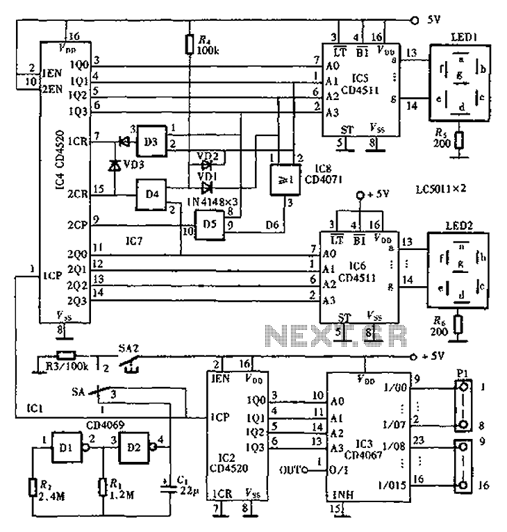
An automatic inspection circuit designed for the simultaneous detection and control of multiple production equipment. This inspection circuit can perform sixteen regular inspections of production equipment. It consists of a pulse generator, multiple inspection circuits, and an automatic inspection...