
Stall-Motor Routing Control Circuits
The described circuit implementations for track routing control in Stall-Motor type switch machines can be categorized into three primary methods: mechanical switching, electronic routing using optoisolators and transistors, and matrix control systems.
The first method employs a 2 Pole - Multi Position rotary switch. This hardware solution allows for straightforward manual control of the switch machine by physically rotating the switch to select the desired track route. Each position on the rotary switch corresponds to a specific route, making it intuitive for operators. The rotary switch typically connects to the Stall-Motor via a set of contacts that energize the motor in the desired direction, thus moving the switch points.
The alternate method utilizes optoisolators and transistors to facilitate electronic control of the routing. In this configuration, the optoisolators serve as a means to isolate the control signals from the high-power switch machine circuits, preventing any potential damage to the control system. When a control signal is received, the optoisolator activates a corresponding transistor, which then powers the Stall-Motor to move the switch points to the selected route. This method offers greater flexibility and can be integrated into automated systems, allowing for remote control and programming capabilities.
The final circuit method described involves electronic matrix control. This system utilizes a decoder to manage multiple routes, enabling complex routing configurations. The matrix consists of a grid where each intersection represents a potential track route. By employing a decoder, the system can select any route based on the binary input signals, thus allowing for an extensive number of route combinations. The limitation of this approach is primarily dictated by the size and complexity of the decoder used, which must be capable of handling the desired number of routes.
Collectively, these methods provide various options for implementing track routing control in model railroading and similar applications, each offering unique advantages based on the operational requirements and desired complexity of the control system.This page shows some methods of track routing control for Stall-Motor type switch machines. The principle method uses a 2 Pole - Multi Position rotary switch while an alternate uses optoisolators and transistors to select the routes. The last circuits on the page are for a method of controlling the matrix electronically. This would, in theory, allow any number of route selections, limited only by the size of the decoder.
🔗 External reference
Related Circuits
A radio remote control system utilizing DTMF (Dual-Tone Multi-Frequency) technology is presented. This circuit allows for the control of various electrical appliances through radio frequency signals. The described radio remote control system employs DTMF tones, which are generated by a...
This ISP programmer can be utilized for in-system programming or as a standalone SPI programmer for Atmel ISP programmable devices. The programming interface is compatible with STK200 ISP programmer hardware, allowing users of STK200 to employ the software, which...
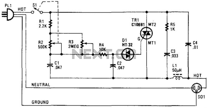
A phase-controlled triac (HT-32) circuit offers control over the effective voltage at the load. It is important to include LI and C4, as they are essential for RFI suppression. The maximum load capacity is approximately 500 W. WARNING: 120...
Below is a thermostat circuit I recently built to control a 1300 watt space heater. The heater element (not shown) is connected in series with two back to back 16 amp SCRs (not shown) which are controlled with a...
The MK484 AM receiver circuit is a simple design based on the MK484 AM receiver IC from Rapid Electronics Ltd. The MK484 is a monolithic integrated circuit that incorporates all necessary sections of an AM receiver, including an RF...
The diagram illustrates a series connection of cell diode capacitors, each rated for an increasing voltage of 300 V. This configuration generates a high DC voltage supply of 40 kV, which can be utilized for various experimental applications. With...