
instrument panel lamp dimmer control
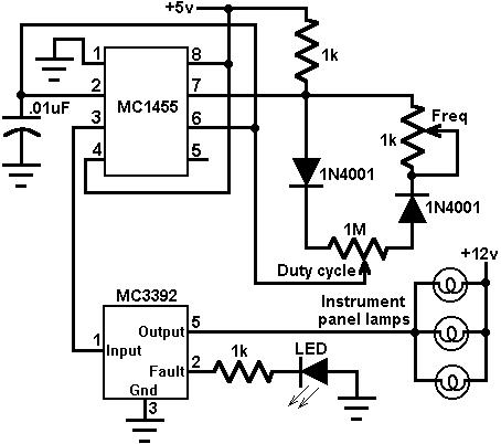
The circuit design integrates an MC3392, which functions as a low-side switch, allowing it to control the current flowing to the automotive panel lamps. The MC1455, a timing circuit, is configured to generate a PWM signal that modulates the duty cycle of the output signal. By varying the duty cycle, the average voltage supplied to the lamps is adjusted, thereby controlling their brightness.
The MC3392 is equipped with built-in protection features, ensuring that the circuit can handle load variations and prevent damage to the components. The low-side switching configuration is advantageous in automotive applications as it helps to minimize electromagnetic interference (EMI) and ensures efficient operation.
The MC1455 is typically configured in an astable mode to produce a continuous PWM signal. The frequency and duty cycle of this PWM signal can be adjusted by changing the values of the resistors and capacitors in the timing circuit. This versatility allows for precise control over the lamp brightness, catering to different user preferences and lighting conditions.
In summary, this circuit effectively combines the MC3392 and MC1455 to provide a reliable and adjustable dimming solution for automotive instrumentation panel lamps, enhancing visibility and user experience while maintaining safety and component integrity.This circuit uses an MC3392 low side protected switch and an MC1455 timing circuit to form an automotive instrumentation panel lamp dimmer control. The brightness of incandescent lamps can be varied by Pulse Width Modulating the input of the MC3392..
🔗 External reference
Related Circuits
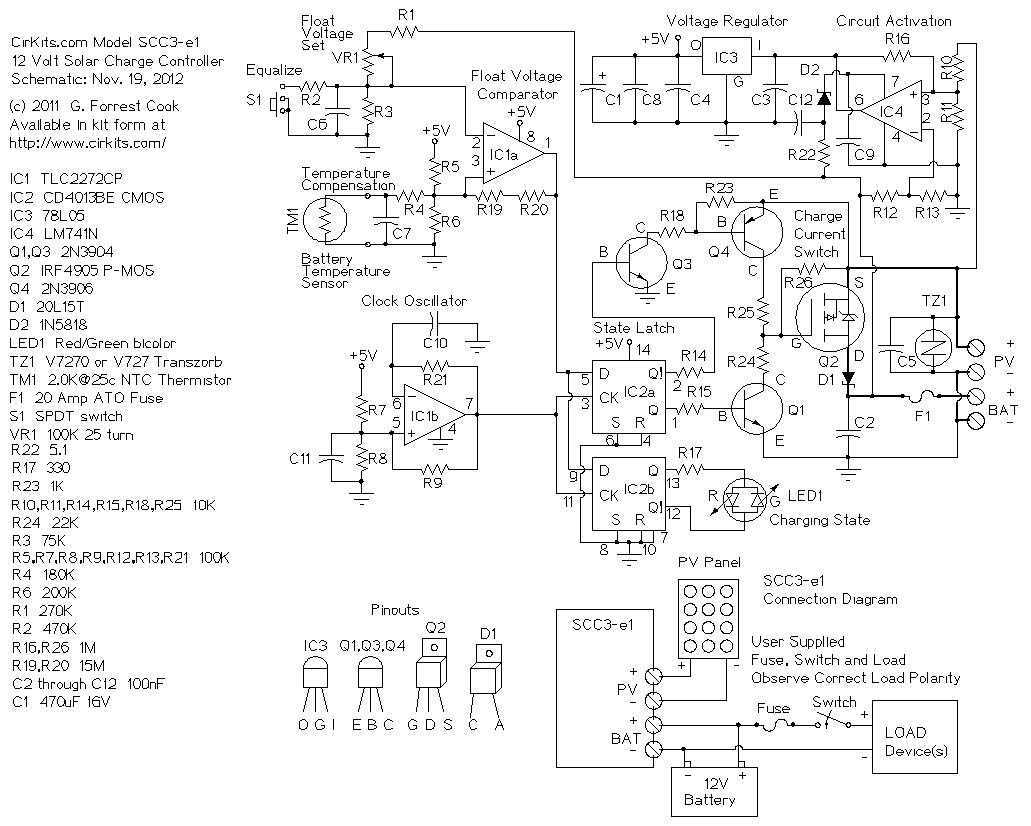
The SCC3 is a solar charge controller. Its function is to regulate the power flowing from a photovoltaic panel into a rechargeable battery. It features easy setup with one potentiometer for the float voltage adjustment, an equalize function for...
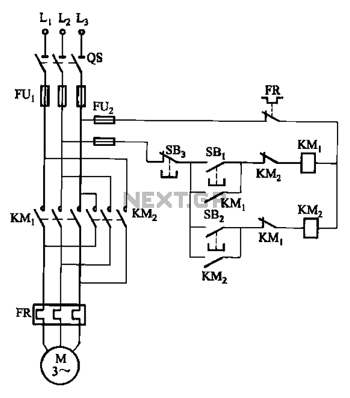
The circuit depicted in Figure 3-22 includes KMi and SBi as forward contacts and forward buttons, KMz and SB2 as reverse contactors and reverse buttons, with SB3 designated as the stop button. The circuit in question is likely part of...
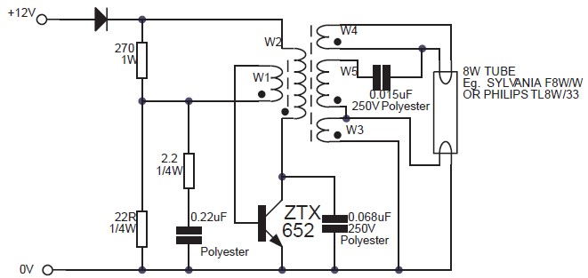
This circuit is an 8W inverter designed to drive an 8W fluorescent lamp from a 12V power supply, utilizing an inexpensive inverter based on a ZTX652 transistor. The inverter operates from power supplies ranging from 10V to 16.5V, achieving...
Security is a prime concern in our day-to-day life. Everyone wants to be as much secure as possible. An access control for doors forms a vital link in a security chain. The Microcontroller based Home Security System can be...

Sip-and-Puff (SNP) controllers are widely recognized devices, often utilized in electric wheelchairs, enabling individuals with limited hand mobility to control their wheelchairs or other devices through inhaling (sipping) or exhaling (puffing) into a straw. The intensity of the inhalation...
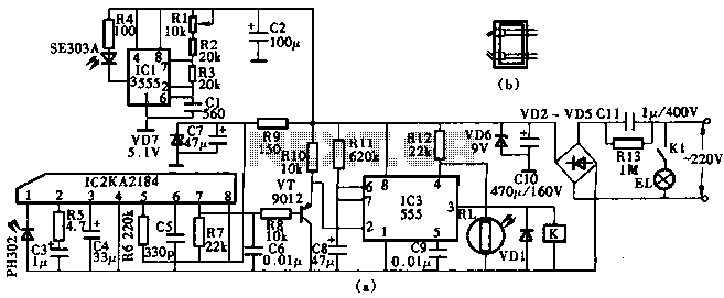
This circuit utilizes the KA2184 infrared receiver ASIC for an infrared remote control dimmer light application, as depicted in the schematic. The infrared signal is generated by a pulse generator using an NE555 timer integrated circuit. The NE555 produces...