
Infrared remote control dimmer light circuit diagram
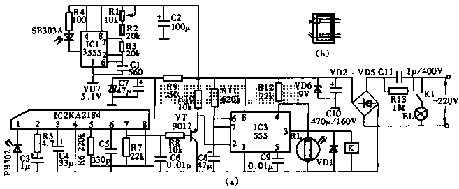
The KA2184 infrared receiver circuit operates by receiving modulated infrared signals emitted by the transmitter. The NE555 timer circuit generates a square wave signal at a frequency of 40kHz, which is suitable for infrared communication. This signal is amplified by the transistor (VT) to drive the infrared LED (SE303), which emits the modulated infrared light. The use of the NE555 allows for flexibility in the design, as multiple variants can be utilized without affecting the overall functionality of the circuit.
The KA2184 integrated circuit is specifically designed for infrared remote control applications, providing efficient signal processing capabilities. It is crucial to ensure that the infrared LED and the receiver are aligned properly to maintain effective communication. The interchangeable nature of the infrared receiver IC (CX20106) allows for easy upgrades or replacements without significant redesign.
The TRIAC (VTH) is employed to control the power delivered to the light source, allowing for dimming functionality. The choice of a small plastic package TRIAC ensures that the circuit remains compact and efficient. The selection of a zener diode (VS) rated at 12V and 0.5W is essential for voltage regulation, protecting the circuit from potential overvoltage conditions.
Overall, this infrared remote control dimmer light circuit is designed with versatility and reliability in mind, suitable for various lighting applications while allowing for component substitutions as needed. Proper attention to component specifications and circuit layout will ensure optimal performance in real-world applications.This circuit uses KA2184 infrared receiver ASIC production infrared remote control dimmer light circuit as shown, wherein the infrared emission from the driving pulse generator NE555 components. Time base NE555 integrated circuit generated 40kHz pulse amplified by the amplifying transistor VT from outside the launch tube infrared emission SE303. Component selection Infrared transmitters when IC selects NE555, VA555, LM555 or SL555 substrate such as an integrated circuit; IC1 should use KA2184 KA2184 infrared transmitter integrated circuit IC2 use infrared receiver IC, its performance parameters and pin functions and CX20106 are identical, It can be directly used interchangeably.
VTH use an ordinary small plastic package Triac, such as 1VIAC94A4 or MAC97A6 other models; VS selection 12V, 0.5W silicon zener diode, such as 2CW60-12V or 1N5242,1N5242B, 1N6002,2CW5242 or UZ-12B models. Other components no special requirements, the choice of models and parameters may be indicated in FIG.
Related Circuits
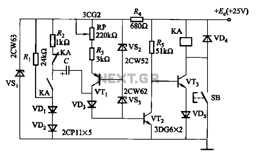
Charging time relay circuit 2 is a long delay circuit. When the capacitor C is 5000 µF, the delay can be up to 1.3 hours. Transistors VT1 and the VS2, VS3 group function as a constant current source to...
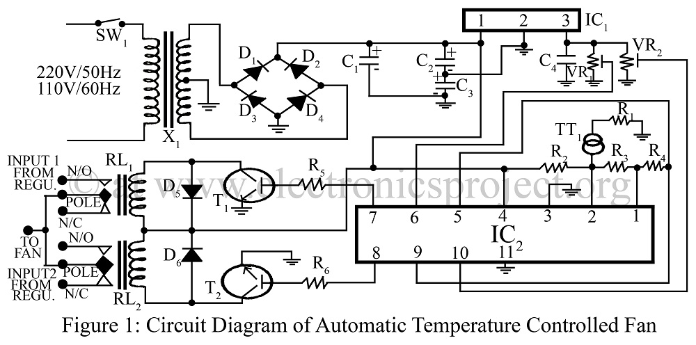
An automatic temperature-controlled fan regulates the fan speed based on temperature variations using the temperature transducer AD590 and an op-amp LM324 circuit diagram. The automatic temperature-controlled fan circuit utilizes the AD590 temperature transducer, which provides an output voltage that is...
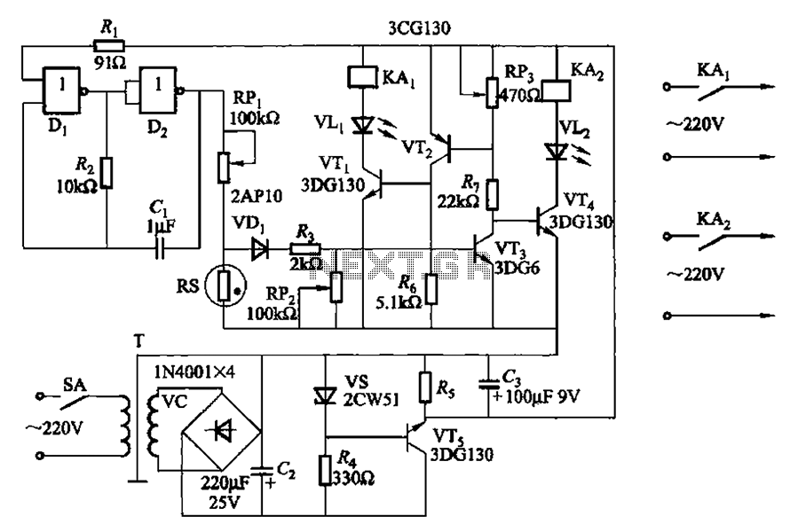
Two NAND gates (Di, Dz) and a resistor (Rz) along with capacitors (C1, etc.) form an RC self-excited multivibrator with an oscillation frequency of 2.5 Hz and an oscillation amplitude of 4 V. This circuit is used as a...
A slice of the SM2965 includes a canonical 80C32 microcontroller, FLASH memory, E2PROM (28SF512), SRAM for static data storage, and a watchdog timer (WDT). The cost performance of the SM2965 is notably high. This device is designed as a...
Using this low cost project, one can reproduce audio from a TV without disturbing anyone. It does not use any wire between the TV and headphones. Instead of a pair of wires, it uses invisible infrared light to transmit...
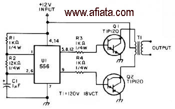
The first section of the 555 timer is configured as an astable oscillator, with R2 and C1 determining the frequency. The output is accessible at pin 5. The second section functions as a phase inverter, with its output available...
Warning: include(partials/cookie-banner.php): Failed to open stream: Permission denied in /var/www/html/nextgr/view-circuit.php on line 713
Warning: include(): Failed opening 'partials/cookie-banner.php' for inclusion (include_path='.:/usr/share/php') in /var/www/html/nextgr/view-circuit.php on line 713