
8W Fluorescent Lamp Inverter circuit
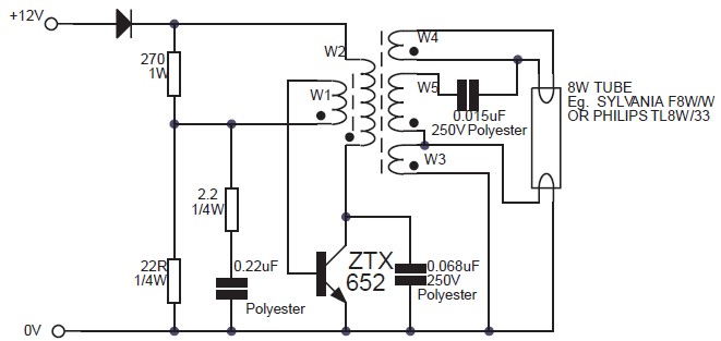
The 8W inverter circuit employs a ZTX652 transistor as the primary switching element, which is critical for converting the low-voltage DC input into a higher-voltage AC output suitable for fluorescent lamps. The design accommodates input voltages from 10V to 16.5V, making it versatile for various 12V power sources, including automotive batteries. The efficiency of up to 78% indicates a relatively low power loss, making it suitable for applications where battery life is a concern.
The separate oscillator design is a notable feature, allowing for frequency adjustments that can optimize performance based on the load characteristics. This flexibility is advantageous when powering devices with different operational requirements. The inverter's capability to drive devices such as electric razors and stroboscopes highlights its practical applications in both household and professional settings.
In contrast, the 1000W inverter circuit based on the RFP50N06 MOSFETs is designed for more demanding applications. The circuit can handle significant loads, making it suitable for larger devices or multiple smaller devices connected in parallel. The use of heatsinks is essential in this design to manage the thermal performance of the MOSFETs, ensuring reliability and longevity during operation.
The inclusion of a square wave generator and amplifier stage in the inverter diagram is crucial for producing the necessary AC waveform. The configuration of transistors Q1 and Q2 as the square wave generator ensures that the output waveform is suitable for driving transformers effectively, while transistors Q5 to Q8 serve to amplify the generated signal, enhancing the output current to meet the demands of the connected load. The transformer plays a vital role in stepping up the voltage from the low DC levels to the required AC levels, making this inverter circuit a practical solution for applications needing AC power from a DC source.This circuit is basically a 8W inverter circuit. The circuit continues to be intended to drive an 8W fluorescent lamp from a 12V power supply, utilizing an cheap inverter primarily based on a ZTX652 transistor. The inverter will operate from supplies in the variety of 10V to 16. 5V, obtaining efficiencies up to 78% as a. This inverter circuit can be used to power electric razors, stroboscopes and flash tubes, and small fluorescent lamps from a 12 volt car battery. In contrast to the usual feedback oscillator type of inverter, the oscillator of this inverter is separate from the output stage, which allows easy adjustment of the oscillator frequency to suit.
Here`s a very simple circuit inverter that converts DC current into AC current, from 12V DC to 220V AC with output power of 5W. Inverter circuit is typically used for emergency lighting, since the power output is small, which is about 5W only.
But you can use this inverter for other purposes that do not. 1000W Power Inverter circuit diagram: This is the power inverter circuit based MOSFET RFP50N06. The inverter capable to handle loads up to 1000W, it`s depended on your power inverter transformer. The RFP50N06 Fets are rated at 50 Amps and 60 Volts. Heatsink is required for cooling the MOSFETs. You may add some MOSFETs with parallel. The following diagram is an inverter circuit which will give you 220V AC 50Hz with maximum power of 100W. This inverter built using transistors both the square wave generator and the amplifier. Inverter Diagram: The Q1 and Q2 used generate square wave. Q5-Q8 amplify the signal and the transformer to increase the AC/square wave current. 🔗 External reference
Related Circuits
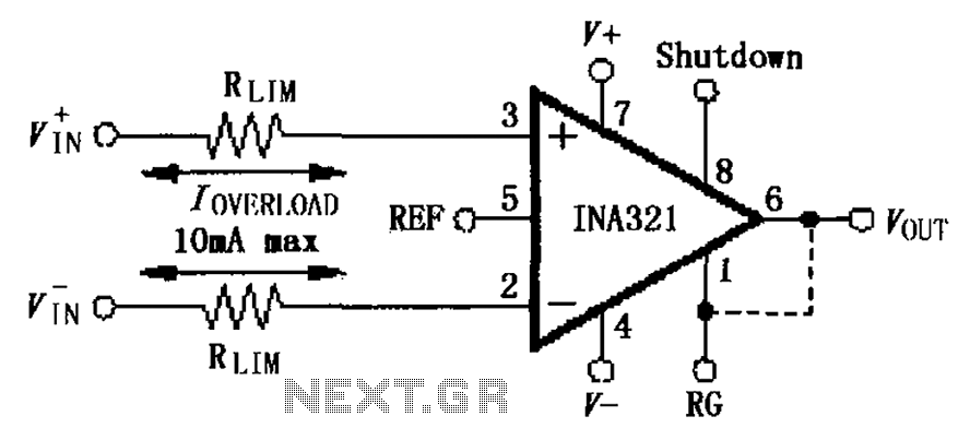
The input current protection circuit for the INA321/322 is illustrated. The INA321/322 features input terminal electrostatic discharge (ESD) protection diodes that become conductive when the input voltage exceeds the supply voltage by 500mV. The protection diodes will conduct, and...

Today, solutions are offered for a timed control relay that utilizes Normally Open (NO) and Normally Closed (NC) contacts to manage the operation of other devices, enabling or disabling them as needed. The functionality of this circuit is based...
The ZN414 integrated circuit (IC) contains a complete automatic gain controlled AM receiver within a compact three-pin package. With only a few external components, it is possible to construct a simple radio that offers excellent selection and reception capabilities....
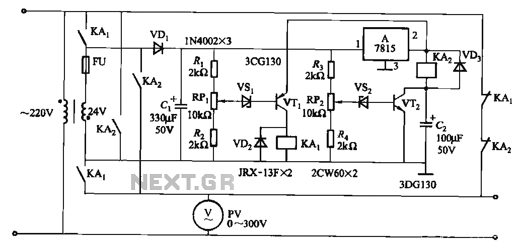
When the input voltage is in the range of 170-260V AC, the output AC voltage falls between 187-231V. The transformer ratio is k = 24/220 = 0.11. If the input voltage drops below 170V, relay KAi activates (adjusted by...

An AC-coupled unity gain voltage follower operating on a single supply is illustrated. The voltage divider network consisting of resistors R1 and R2 provides a DC voltage equal to half the supply voltage to the non-inverting input of the...
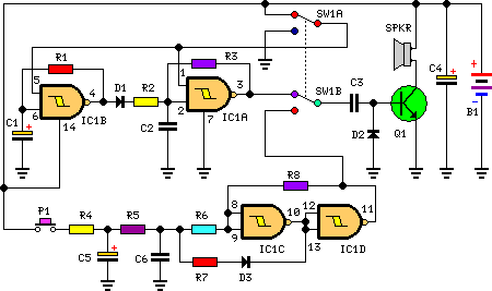
This circuit is designed for children's entertainment and can be installed on bicycles, battery-powered cars, motorcycles, as well as models and various games and toys. When switch SW1 is positioned as indicated in the circuit diagram, it generates the...
Warning: include(partials/cookie-banner.php): Failed to open stream: Permission denied in /var/www/html/nextgr/view-circuit.php on line 713
Warning: include(): Failed opening 'partials/cookie-banner.php' for inclusion (include_path='.:/usr/share/php') in /var/www/html/nextgr/view-circuit.php on line 713